Aquaveo & Water Resources Engineering News

GMS MODFLOW and ArcHydro Training in Yerevan, Armenia

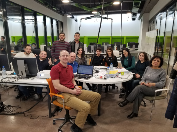
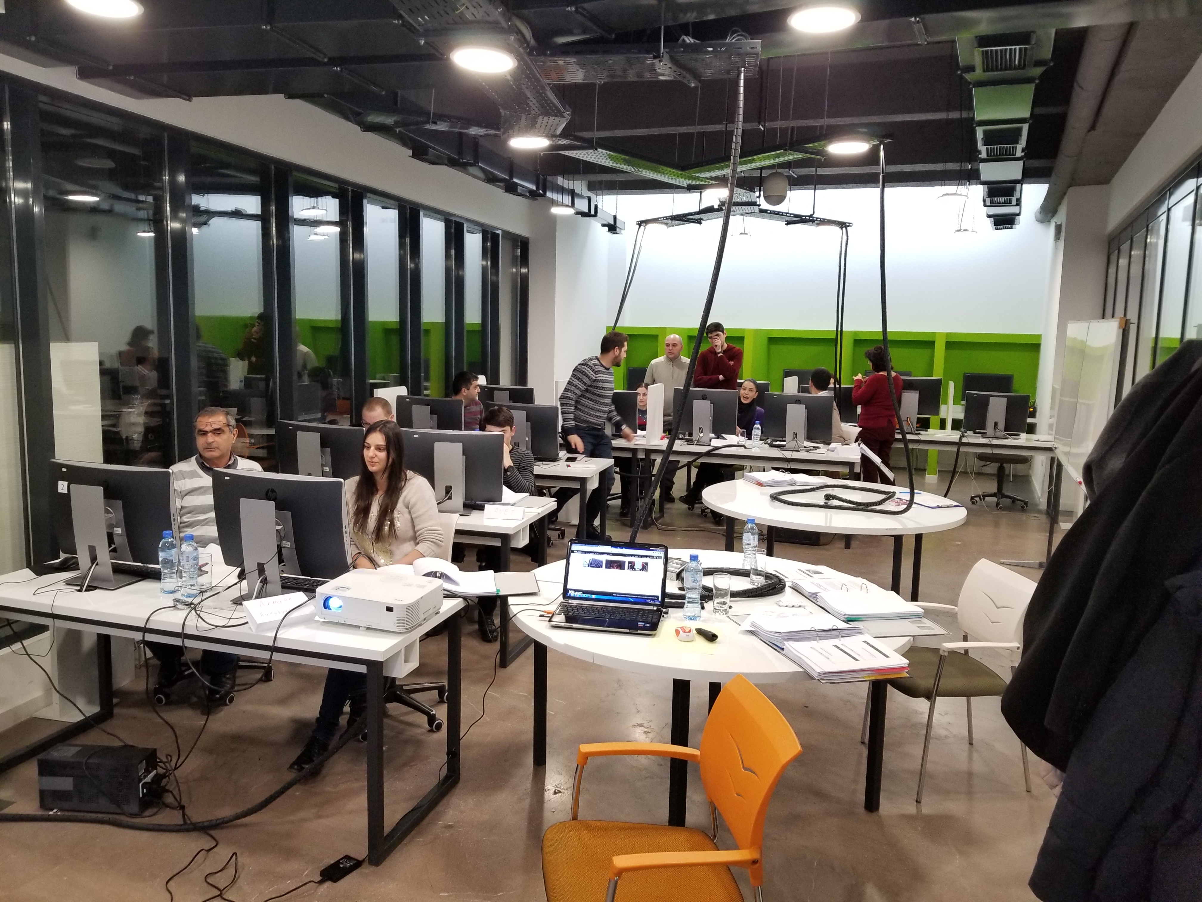
In January, Aquaveo sent Alan Lemon to Yerevan, Armenia to conduct a training course on using MODFLOW in GMS, and using ArcHydro Groundwater. The training covered the basics of using both GMS and ArcHydro Groundwater, as well as some specifics on how these tools could be applied in Armenia to help increase the efficiency of groundwater resource management. These trainings are very hands-on, which helps the participants more quickly learn how to use the tools.

Topics demonstrated and discussed included learning how to build customized AHGW geodatabases, and how to import, manage, and visualize various types of data for structures such as boreholes. The training also covered importing, editing, and visualizing 2D and 3D hydrogeologic models complete with cross sections and maps showing water levels and quality.

Members of the course included representatives from the Water Resources Management Agency and the Environmental Monitoring and Information Center of the Ministry of Nature Protection (MNP), Institute of Geological Sciences of the National Academy of Sciences of Armenia, the International Agribusiness Teaching Center at Armenian National Agrarian University, the American University of Armenia, and Yerevan State University.

This training was arranged by ME&A (Mendez England & Associates) as part of their ASPIRED (Advanced Science & Partnerships for Integrated Resource Development) program. We appreciate their help in arranging the training, and we appreciate the time and effort of all of the ministry and university participants. Despite having to work through a translator, all of the participants were focused and engaged, and a good rapport was developed.

We had a very enjoyable time there. To schedule your own onsite training course, visit the Aquaveo site today.

Blog tags: 

3 Great Features in SMS 12.3 Beta

Every new version of software comes with many new features and updates. The release of SMS 12.3 Beta is no different, with scores of updates and tweaks to make the user experience better. Most of these changes are behind the scenes, but we’d like to highlight three features which will prove very useful to our users.

1. Generating an observation arc plot

Right-clicking on an arc in an observation coverage now has the option to directly generate an observation profile plot from the selected arc. This allows you to see the elevations for the stream at that location. It is also faster than using the Plot Wizard. Simply use the Select Feature Arc tool to right-click on the specific arc and select Show Observation Plot.

2. Transparency options for filled polygons in the Map module

A transparency can now be set for filled polygons in the Map module. This means that materials coverages and other filled polygons can be better aligned with other coverages and GIS data such as background maps. Open the Display Options dialog, select "Map" from the list on the left, and turn on Fill in the Polygon section to access the Transparency slider.

3. Setting the Default Contour Range options

Some models include spin up or ramp times during which the numerical results are not within a typical range. This option provides a method for instructing SMS to skip these atypical or unreasonable values from impacting the default ranges of the contours computed.

Select Edit | Preferences… to bring up the Preferences dialog, then click Default Range Options in the Transient Contours section of the General tab to bring up the Default Transient Contour Range dialog. The dialog allows the first n time steps or hours to be skipped when creating the contour range, or to use the current time step.

Try out these features today by downloading the SMS 12.3 Beta.

Blog tags: 

Take Advantage of the Cloud for Engineering

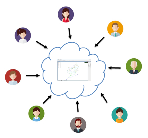
These days, everything seems to be in “the cloud”, and for good reason. No more having to email or manually deliver a flash drive or DVD containing the documents or data. Having it stored in one online location accessible to everyone on the project makes everything more convenient, and makes it far easier to collaborate with others in your organization.

As an example a cloud-based application, you can use CityWater on the Aquaveo Portal, to access municipal water distribution data from anywhere using a modern web browser. One person uploads an input file for the model which can then be accessed by anyone in the organization.

Once the model has be uploaded, you and your colleagues can create multiple scenarios to generate alternate models. This allows quick collaboration for group planning of municipal water distribution projects. Feedback and comments can be made from multiple contributors to help everyone have their say. CityWater does all this while maintaining the integrity and security of the original model.

Your whole process becomes much simpler because the CityWater controls are designed from the ground up to scale from desktop to tablet to smart phone, all without removing any of the functionality. So, whether you’re in your office or out on a work site, the relevant data can be easily accessed with just a few taps. New and updated information can also be entered on the fly to make the model results more specific and accurate.

Because it doesn’t have to be purchased and installed on every computer or device, CityWater is much more cost effective. This allows the cost per user to be significantly lower, and your IT department won’t be burdened with additional work. The software behind CityWater is regularly updated, so anytime you log in through the Aquaveo Portal, you are using the most current version.

Try out the CityWater tool today by going to the Aquaveo Portal. Use “trycitywater” as the username and password.

Blog tags: 

6 Ways to Select 3D Cells

When using a 3D grid in GMS, it’s likely you will need to select a grid cell at some point in the project. This is usually a straightforward procedure. However, sometimes the 3D nature of the grid makes it less obvious as to which cells are selected.

To cover the basics of selecting cells, here are six ways to select 3D grid cells in GMS.

1. Select Cells Tool

The Select Cells tool is the most obvious choice and the tool most often used to select cells in a 3D grid. The tool can be used to select multiple cells by clicking and dragging a box over a group of cells. Multiple cells can be selected by using using the Shift or Ctrl keys. Select one cell, hold down the Shift key, and select a second cell to select both cells and all the cells in between. If you want to select cells without getting all the cells in between, use the Ctrl key.

Using the Select Cells tool only selects the visible cells, so be certain you are on the correct layer of your 3D grid. It will not select the cells underneath.

2. Select i, Select j, and Select k Tools

These tools are a lot like the Select Cells tool and operate in a similar way. The only difference is these tools will select entire rows or even entire layers. These tools depend on the view you are in and the layer being shown.

For example, if using the Select i tool, one or more rows can be select when in plan view. Only rows on the visible layer will be selected. When switching to a front view, the Select i tool will select all visible cells because all of the cells are active in the i direction of the 3D grid.

Unlike the Select Cells tool, the Shift key functions like the Ctrl key when selecting multiple rows of cells.

3. Select All

This tool does what it says. The Select All command under the Edit menu, will select all visible cells in the 3D grid. If the view is changed (e.g., from front view to plan view), all cells will be deselected. This command can also be accessed by pressing Ctrl+A on your keyboard.

4. Select With Poly

Dragging a box over a group of cells is nice, but sometimes you need a little more precision. Using the Select With Poly command in the Edit menu will let you click out a polygon shape to define your selection area. Double-clicking ends the process and reverts back to whatever tool you had previously selected.

5. Select By ID

Do you have a specific cell you want to select, for example the location of a well or perhaps you received an error message about a cell when running a model check? If you know the cell ID or the location, you can use the Select By ID command under the Edit menu. This brings up the Find Grid Cell dialog where you can enter the cell ID or location. When done, you’ll find the cell has been selected. This tool does require that the cell be visible in the Graphics Window.

6. Select By Dataset Value

Sometimes there is a range of cells you’d like to select which contain a specific set of values. This can be done by using the Select By Dataset Value command in the Edit menu. Be certain the dataset with the values you want to select is active before using this command. It will bring up the Select by Dataset Value dialog where you can specify selecting cells with a certain value range.

There are other ways to select cells in GMS, but these are the most common methods. Check out the selection options for 3D grids in GMS today!

Blog tags: 

How to Use TauDEM in WMS to Define Flow Paths

Using a watershed delineation tool is one of the first steps in creating a usable model for any sort of watershed, whether for conservation of natural resources, further development of a municipal drainage system, or determining potential flood zones. Tools such as TauDEM can make the process much simpler by basing those calculations off an existing DEM.

The process is generally straightforward:

  1. Import a DEM for the area in question.

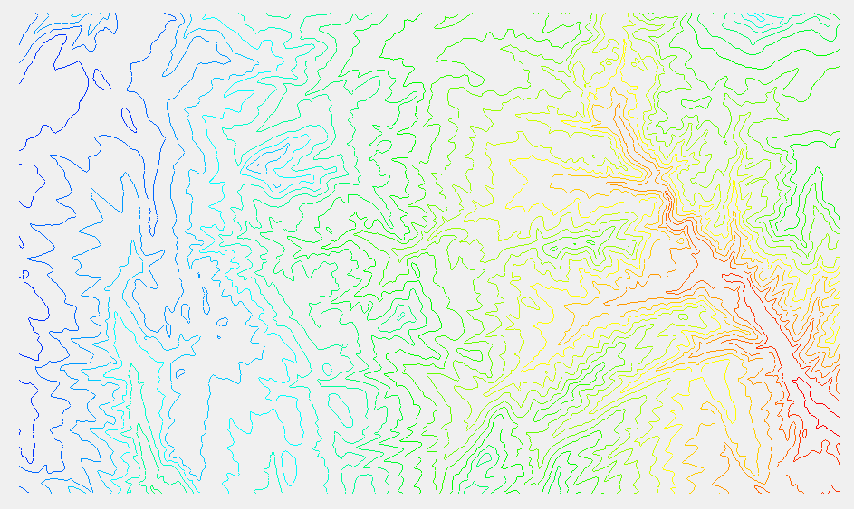
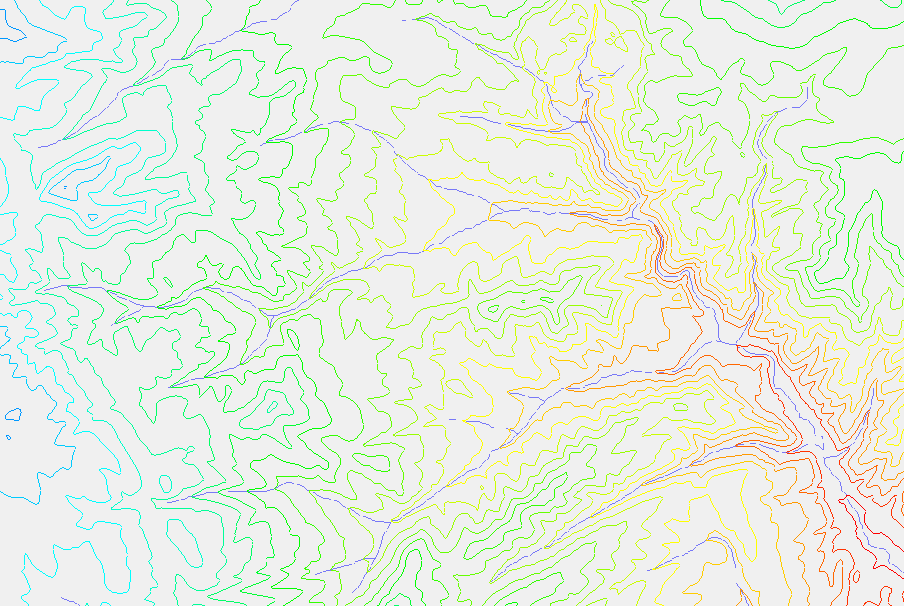
    DEMs can be obtained many different ways. They can be imported directly using the features in WMS, they can be downloaded for free from the USGS and other governmental sites, or they can be created by you using lidar or similar tools. This is the DEM used in this example:

  2. Once the DEM is imported, activate the Drainage module.
  3. Select DEM | Compute Flow Direction/Accumulation... to bring up the Flow Direction/Accumulation Run Options dialog.
  4. Select Run TauDEM under Select the model to determine the flow direction/accumulation.
  5. If you want to use multiple processors, check the box next to Use MPICH2 and enter the number of processors.

    If you don’t know if your computer has multiple processors, simply leave the box unchecked.

  6. If this is your first time running MPICH2, click Register MPIEXEC and enter your username and password at the prompt. This should be your Windows username and password.
  7. Click OK to close the Flow Direction/Accumulation Run Options dialog and bring up the Units dialog.
  8. Set the units to be appropriate for the location of the project and click OK.

    The watershed delineation process can take some time, depending on the size of the area being delineated and the computer being used. Once TauDEM has finished delineation, the cells accumulating the flow will appear.

  9. When TauDEM is finished running, click Close to exit the Model Wrapper dialog.

TauDEM is part of the Community Edition of WMS, so you can try out this feature today.

Blog tags: 

How to Make an Unstructured Floodplain Mesh

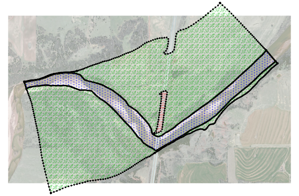
Flooding can cause significant--and sometimes devastating--damage to infrastructure, crops, and commercial, residential, and industrial buildings. Unstructured floodplain meshes can be used to anticipate the most likely scenarios and plan prevention and mitigation accordingly. These are only some of the reasons why an unstructured floodplain mesh might need to be created. Your project may include multiple low lying areas that historically flood. You may need to see where berms or channels need to be adjusted to better accommodate sudden flow increases and prevent or mitigate flooding.

There are a few steps that should be taken anytime you model and simulate an unstructured floodplain mesh. SMS simplifies this process.

1. Import Background Data

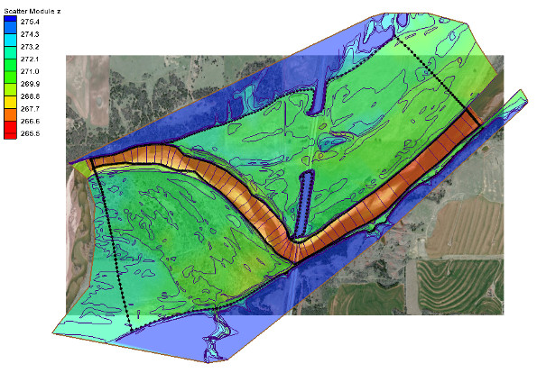
The first step is usually to import elevation data from a scatterpoint dataset, raster objects, lidar data, mesh, grid, or from an existing project that includes the required elevation information for the floodplain. If the elevation data is not from a scatter set, it will need to be converted to a scatter set or interpolated to the mesh after the mesh is generated.

An aerial photo of the area can also be imported to help with visually referencing rivers, roads, and other structures.

2. Create a Mesh Generator Coverage

Once the elevation data has been imported, create a mesh generator coverage by right-clicking in the Project Explorer and selecting the New Coverage command. From the New Coverage dialog, select the Mesh Coverage type and enter a name for the coverage.

3. Create Feature Objects

The unstructured floodplain mesh will be generated from polygons in the mesh generator coverage. On the mesh generator coverage, create the enclosed arcs encompassing the area of the floodplain using the Create Feature Arc tool. Turn the enclosed arcs into a polygons by using the Build Polygons command.

4. Assign Mesh Type and Bathymetry

Use the Select Feature Polygon tool to double-click on each of your polygons. In the dialog that appears, assign the mesh type you want to create. You can use the Preview Mesh button to ensure your mesh will generate correctly.

After selecting the mesh type, select constant value or scatter set to use as the mesh elevation.

Once this is done for all your polygons, you are ready to generate your unstructured floodplain mesh.

5. Generate the Unstructured Floodplain Mesh

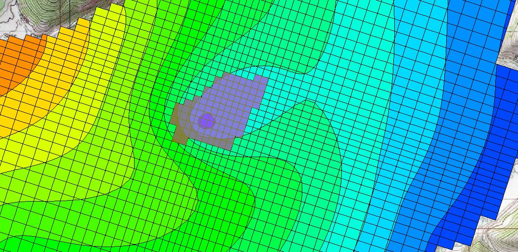
The process of generating your mesh is quite simple if the above processes are followed. Simply right-click on the mesh generator coverage and select the Convert to 2D Mesh command. SMS will start the calculations to create the mesh. Older versions of the software will bring up an options dialog where a few changes can be made to how the mesh is generated. For most projects, the default options are acceptable. A dialog will then appear asking you to name your mesh—the final step in creating the mesh.

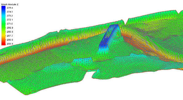
Now you have an unstructured floodplain mesh. Explore the mesh to see if you like the results and get started on the rest of your project. You can adjust the display options at this point to make sure your mesh is satisfactory.

You can try out creating unstructured floodplain mesh generation in the SMS Community Edition for free.

Blog tags: 

GMS 10.3 Beta Now Available!

A beta version of GMS 10.3, the next version of GMS, has been posted on our downloads page. This release includes a new model interface (MT3D-USGS), a much improved model interface (mod-PATH3DU), and lots of other enhancements, many of which were specifically requested by users. The full list of What's New can be found on the wiki, but here's a brief summary of some of the more noticeable changes.

Bigger icons for hi-res displays
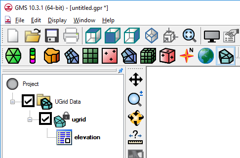
One of the most immediately noticeable changes will be the new icons. The icons in GMS looked very small on some newer, higher resolution displays, so we've added larger versions of all the icons and GMS automatically switches to use the larger icons when it is run on a hi-res device. This effort involved an overhaul of almost all of our icons and some of them look noticeably different.

MT3D-USGS

This is a new model from the USGS which includes, among other things, transport calculations through the unsaturated-zone. GMS 10.3 includes an interface to MT3D-USGS and the interface is similar to those of the other flavors of MT3DMS.

mod-PATH3DU

The mod-PATH3DU interface has been improved and taken out of beta. Support for mod-PATH3DU version 1.1.0 including the new Waterloo method was added, as well as support for specifying DefaultIFACE, a model checker and a model wrapper, and the ability to create starting locations using a UGrid. More export options were also added including exporting pathlines to a shapefile.

MODFLOW Support

MODFLOW 6

The USGS recently released the next version of MODFLOW, MODFLOW 6, in beta and we are working hard to add support for it in the next version of GMS. For GMS version 10.3, however, the only MODFLOW 6 support is the ability to open a MODFLOW discretization file (.dis) and create a UGrid. Look for a more complete interface in the next version.

Map Shapefile to CLN

We've added the ability to create a CLN (connected linear network) from a shapefile. The CLN process is part of MODFLOW-USG but up until now it has not been easy to create this data in GMS. Using a 2D or 3D shapefile, GMS can automatically intersect the shapefile with the grid and create the CLN data. A new tutorial was created to demonstrate how this is done.

Zone flow for MODFLOW-USG ZoneBudget

Prior to version 10.3, GMS did not calculate the flow between zones or between selected cells for MODFLOW-USG models as it did with other versions of MODFLOW. This has now been implemented for MODFLOW-USG.

DISU data not recalculated

The DISU package data was being recalculated every time the model was saved, even if nothing had changed. This data can take a long time to calculate and save, so now GMS 10.3 will only recalculate the data if it needs to due to a change. For models that were created outside of GMS, the DISU data is never recalculated because the unstructured grids are often not suitable for these types of calculations (ie. vertices are not shared). The result is that these models are better supported in GMS because GMS no longer overwrites the correct DISU data with garbage data.

UGrids

Display Options per UGrid
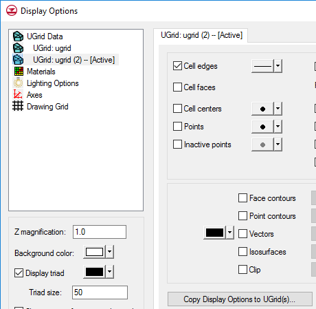
Each UGrid can now have it's own display options. All of the UGrids are now listed in the Display Options dialog. Default UGrid display options are also available, which new UGrids inherit from. Options for one UGrid can be copied to other UGrids.

Splitting Layers

The ability to split a UGrid layer has been added, and is similar to this feature for 3D Grids.

Notes

As mentioned in a previous blog post, a new feature called "Notes" has been added which allows you to add notes to almost any object, including the project itself. This is meant to help document the modeling process as the model is being built. GMS can also automatically create notes about how new items were created. Notes include a timestamp indicating when the note was created.

Many other enhancements are included in GMS 10.3, including four new tutorials and lots of user requests. Some things are still not fully tested or complete, hence the "beta" status, but you are welcome to download GMS 10.3 and give it a try. Your feedback is welcome at support@aquaveo.com.
Blog tags: 

MT3D-USGS in GMS 10.3

GMS 10.3 will include preliminary support for MT3D-USGS, a new transport model from the USGS that is based on MT3DMS and which allows for transport through the unsaturated zone, among other things. Here's a simple animation made in GMS showing a contaminant dropping through the unsaturated zone, hitting an aquitard, and spilling over the edges. This animation is based on a new tutorial that will be included with GMS 10.3 on how to use MT3D-USGS in GMS.

Animation of contaminant spill.

GMS 10.3 Coming Soon

It's been awhile since we posted any sprint reports, but that doesn't mean we've been enjoying a long vacation. GMS 10.3 is getting close to being done and the list of new features has been put on the wiki. There are a number of MODFLOW improvements, support for MT3D-USGS, major improvements to mod-PATH3DU (particle tracking for unstructured grids) and lots of other things including many user requests.

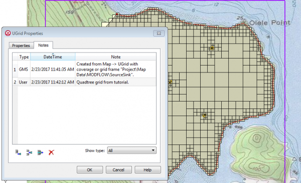
One user requested feature that will be in GMS 10.3 is the ability to add notes in various places in GMS. Notes can be added to objects like UGrids and coverages or to the project itself to help model developers remember where things came from or why they did things the way they did. GMS adds some notes automatically, like when an object is created from another object, like Map -> UGrid. All the notes can be shown, or just the user-created notes, or just the GMS-created notes. Here is an example of what it will look like.

GMS Sprint July and August 2016

Some of the more notable things completed by the GMS team during the month:

  • Multisampling (antialiasing) added in preferences
  • Fixed several bugs
  • Finished clip tool
  • Progress on new lidar functionality
  • Lots of refactoring
  • Released GMS 10.2 in beta
  • Documented new 10.2 features on the wiki
  • New notes functionality finished (in dev)
Blog tags: 

Pages