Aquaveo & Water Resources Engineering News

Importing Land Use and Soil Type into WMS

Have you needed to obtain land use or soil type data for your WMS project? Land use, or land cover, data is used to define the land use or cover of areas in the watershed such as urban, forested, farm, etc. Soil type data is typically used to control the movement of water in a watershed model. Data for land use or soil type can be added to your watershed project in WMS by using files on your computer or by downloading the data from a database.

Import a File

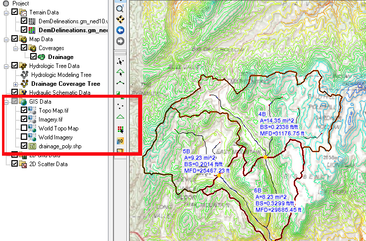
Files containing land use or soil type data are often contained in a shapefile, though other formats are possible. This file can be imported from your computer using the File | Open command. Once imported, the shapefile will appear in the GIS Module. It will likely need to be converted to the map coverage before being used in your watershed model.

Import From Web

Land use or soil type data can be obtained from online web services. To access these services, do the following:

  1. Select File | Add Data | Get Data from Map.
  2. In the Virtual Earth Map Locator, select the location of your project. If your project already has a set projection, then the location of your project should already be visible.
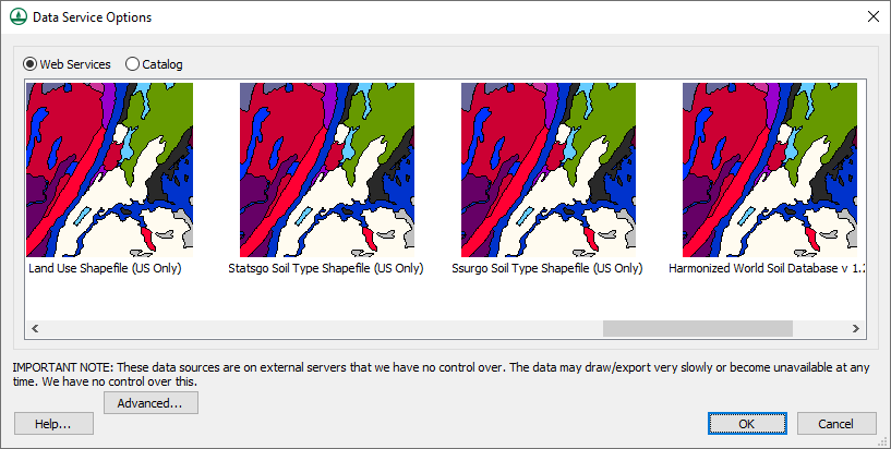
  3. In the Data Service Options dialog, select one of the web services containing land use or soil type data such as the Land Use Shapefile, Statsgo Soil Type Shapefile, or Harmonized World Soil Database.
  4. Save the land use or soil type data to your computer. The data will automatically be imported into your project as a shapefile in the GIS Module.
Data Service Options dialog showing land use and soil type options
Moving Land Use and Soil Type Data

In most cases, having land use or soil type data on a shapefile will not include the data in your watershed model. Most often the data will need to be moved from the shapefile to the Map module. To do this:

  1. Create a map coverage with the Land Use or Soil Type property. Land use data should be placed on a land use coverage and soil type data should be placed on a soil type coverage. Data may be lost if the wrong coverage type is used.
  2. After creating the correct map coverage, select the land use or soil type shapefile in the GIS module then select the Mapping | Shape to Feature Object command.
  3. When using the GIS to Feature Objects Wizard, select correct map coverage and make certain all of the attributes are correctly assigned.

Once you have imported land use or soil type data and it has been correctly converted to the Map module, it is ready to be used in your watershed model. Try out using land use and soil type data in WMS today!

Blog tags: 

Observation Arcs vs. SRH-2D Monitoring Lines

Have you ever wondered what is the difference between using an observation arc and using an SRH-2D monitoring line? Both make use of arcs drawn on map coverages and both are used to show the results of a model run. While they serve a similar purpose, there are significant differences between the two. This article will discuss some of these differences.

Observation Arcs

Observation arcs are made on an observation map coverage. This generic coverage can be used with nearly every numeric model in SMS. It is not specific to only SRH-2D. Observation arcs can be used to generate a profile plot based on the model run results. SMS does this by interpolating the results to locations along the observation arc.

An observation arc can be created before or after the model run. The arc can also be adjusted after the model run to change what is shown in an observation plot.

SRH-2D Monitoring Lines

SRH-2D monitoring lines are created on an SRH-2D monitor coverage. This is an SRH-2D specific coverage that will only work with an SRH-2D simulation. The monitor coverage must be included in the SRH-2D simulation during the simulation run in order for the monitoring lines to produce results. A plot from the monitor line can be viewed in the Simulation Run Queue during the model run.

When creating monitoring lines, arcs are drawn on the SRH-2D monitor coverage. It is important to pay attention to how these arcs snap to the SRH-2D mesh. Monitoring lines will follow the nodes of the mesh instead of interpolating to the location of the arc. For SRH-2D, this makes the results of the monitoring lines more accurate than observation arcs.

SHR-2D monitor lines snappingto mesh nodes

The results from the monitoring lines are found in the the *.dat file that starts with “LN”. If a change is made to a monitoring line after the simulation run, the simulation will need to be saved and run again to get the new results for the monitoring line.

Using both monitoring lines and observation arcs is common for many projects. Keeping in mind the differences will help you make better use of both of them. Try using observation arcs and monitoring lines in SMS today!

Blog tags: 

Tips for MODFLOW 6 in GMS 10.5 Beta

Have you had a chance to use MODFLOW 6 in the GMS 10.5 Beta? If you have, you may have noticed that MODFLOW 6 operates a little differently than other versions of MODFLOW. This is to allow for some additional tools and options.

When using MODFLOW 6 in GMS 10.5 Beta, here are a couple tricks to try out.

Having Multiple MODFLOW 6 Simulations in the Same Project

You can create multiple simulations in the same project by using the simulation workflow in GMS 10.5 beta. This is particularly useful when attempting to calibrate your project. The way this is done is by doing the following:

  1. Right-click on the simulation in the Project Explorer and select the Duplicate command. This will create a duplicate of the simulation that includes all the same parameters and uses the same grid.
  2. On the new simulation, change the parameter that needs to be calibrated, such as the head values or the pump values of the wells. It is generally best to only focus on one parameter change when calibrating the model.
  3. Run the new simulation and compare the results between the different simulations.
  4. Repeat this process with additional simulations to calibrate the model.
Duplicate command in the simulation menu
Running Multiple Simulations at the Same Time

After you have created multiple MODFLOW 6 simulations, you can run all of the simulations at once. This is done by doing the following:

  1. Right-click on the simulation folder and select the Save All and Run command.

The Simulation Run Queue dialog will display all of the simulation model runs. While the simulations are running, the Simulation Run Queue can be moved aside or minimized to allow you to keep using GMS. The results can be loaded into the project for you to review when the simulations have finished.

Sae All and Run command in the simulation folder menu

Additional features for MODFLOW 6 are still being added to GMS and will appear in future versions of the software. For now, check out MODFLOW 6 in GMS 10.5 beta today!

Blog tags: 

Sharing WMS Project Files

After completing your project in WMS, are you needing to share your project files with a client or colleague? When doing this, it is important that you send them all of the files related to the project. All of the files for the project should be shared in the same folder. This article will go over some of the important files to include.

The most important file to share is the WMS XMDF Project File (*.wms). This file contains many elements of your project, but also acts as a directory for the other files being used by your project. To improve application performance, the WMS project file does not contain all of the data necessary to open the project, so it is important to include all relevant files when sharing your project.

In addition to the WMS project file, it is important to include GIS files that are in the project. This would include any shapefiles, image files, raster files, or projection files. WMS will ask you to locate these files if they are not in the same directory as the WMS project file when the project is opened. If the GIS files are no longer relevant to the project, they should be removed from the project before saving and sharing the WMS project file.

GIS items in a WMS project

Another file that is important to include is the map file (*.map). This file contains all data related to feature objects and map coverages in the project. Without it, many projects may be unable to open. Similarly, the tree file (*.tre) is necessary to import hydraulic and hydrologic data. Grid (*.grd) are needed to import grid geometry.

When a model run has been completed, it is important for the solution (*.sol) and output (*.out) files to be included with the project file. Without these, whoever receives the files will be unable to see the results of your model run.

Finally, be certain to include model specific files, such as those for HEC-HMS or GSSHA. Refer to the model documentation for information on these files.

One trick to help include all files in your project, is to use the Save As command and save the project to a new folder. Then make certain to move that folder to a new directory and open the project file to see if any files are missing.

Now that you know a little more about WMS files, try sharing your WMS projects today!

Blog tags: