Aquaveo & Water Resources Engineering News

Incorporating Geology into a MODFLOW Model

Have you created a MODFLOW model and would like to incorporate geological features in between the MODFLOW layers?

The first step is to create the solid to be used. In GMS, solids are representations of stratigraphy used for site characterization and visualization. Solids can be created in any one of three ways:

  1. Convert horizons to a solid.
  2. Convert one or more TINs to a solid.
  3. Manually create a solid by right-clicking in the Project Explorer and selecting the desired type of solid from the New | Solid menu.

Using the first two methods will allow the solid material composition (what the solid is made of) to be automatically interpolated from the horizon or TIN information. Using the third method will allow you to select the material for each solid reated. The third method also requires knowledge of the XYZ coordinates and other attributes, depending on the type of solid being created (cube, cylinder, sphere, or prism).

Once you’ve created your solids, these steps will integrate the solids into the MODFLOW model:

  1. Right-click on the grid and select Classify Material Zones… to bring up the Classify Material Zones dialog.
  2. Select the solids folder you just created.
  3. Select the Classify algorithm you want to use.
  4. Enter the name of the material set being created.

The Centroid algorithm assigns the solid to the cell if it passes over the centroid of the cell. The predominant material algorithm assigns the solid to the cell if it is the predominant material in the cell (the material making up the highest percentage of the cell). This method maintains your grid, while interpolating the materials to the grid, so that you can have multiple materials within a layer.
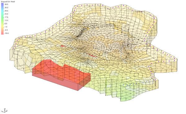
Try adding solids to your MODFLOW models in GMS today!
Blog tags: 

Working with Rain Gages in GSSHA

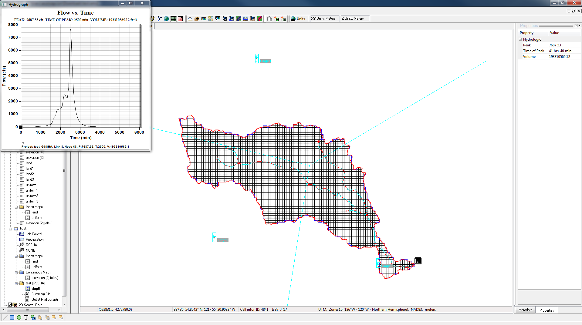
Are you needing to add rain gages to your GSSHA model? Using rain gages to define your precipitation in GSSHA is extremely useful due to its ability to spatially model precipitation over a watershed. Combining spatially varying rainfall with the distributed parameters of GSSHA is a great way to create a fairly realistic model for your watershed.

One of the bigger challenges when simulating a storm event is finding reliable data. Although it is important to investigate the most accurate source for your particular watershed, there are websites containing NOAA and GLDAS data for not only the United States, but globally. Having many sources of compiled data all on one site makes Cuahsi’s HydroClient a very useful resource. For those using our software internationally, another possibly useful resource when gathering storm data from the Global Precipitation Climatology Centre. This gives monthly values from 1901-2013, with newer data being added frequently.

Now that you have solid data for your watershed, it is time to define your gages. To use rain gages as your precipitation input:

  1. Create a rain gage coverage.
  2. Create rain gages in their proper locations.
  3. Using the Select tool, double-click on the gage to bring up the Rain Gage Properties dialog.
    1. Set the gage type to GSSHA.
    2. Define the precipitation using either a cumulative or an incremental distribution.
    3. Beneath the Show drop-down, choose GAGES if your data is incremental, and ACCUM if your data is accumulative.
  4. Return to the 2D-Grid module and select GSSHA | Precipitation.
    1. Select Gage as the rainfall event, select Rain Gage, and choose your preferred interpolation method (Inverse distance weighted or Thiessen polygons).

For more information and specifics on working with gages in GSSHA, please take a look at the GSSHA user’s manual. WMS provides a useful and helpful resource when creating a GSSHA model, analyzing and viewing the results. Practice using rain gages as your precipitation source in WMS 11.0 today!

Blog tags: 

New Bridge Scour Tool in SMS 13.0

You are probably aware of the potential destruction caused by bridge scour. Up to 60 percent of bridge failures in the United States from 1950 to 1989 were caused by scour. Bridge scour occurs when the stream bed material around bridge piers is eroded. This can leave the pier unsupported by the stream bed, causing it to collapse.

Recent news has shown bridges of all sizes all around the world collapsing or in danger of collapsing due to scour. Such failures can have a huge negative impact on the economy and also pose a danger to the lives of those who use the bridge regularly. The Federal Highway Administration (FWHA) advised that it is far less expensive to take measures to prevent scour than to replace a bridge that fails due to scour.

Part of the scour mitigation process is evaluating countermeasures that can be taken to prevent such failures. These include onsite surveys and inspections, physical modeling such as that done at the FWHA Hydraulics Laboratory at the Turner-Fairbank Highway Research Center in McLean, Virginia, and computer modeling using tools such as the Surface-water Modeling System (SMS) from Aquaveo.

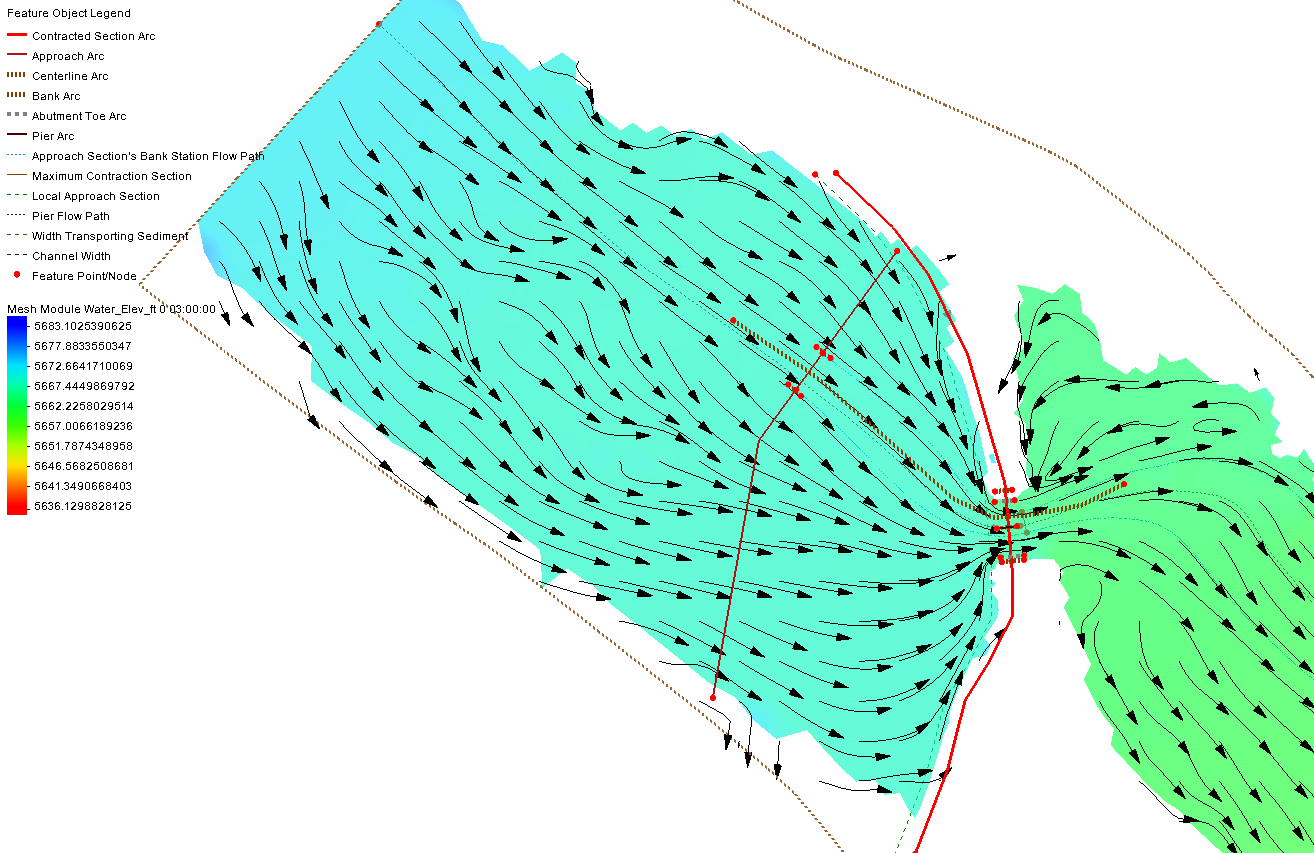
SMS 13.0 adds powerful new post-processing Bridge Scour tools that can be used to quickly test the scour effect of different pier arrangements, pile sizes and shapes, and vessel impact protection structures such as dolphins and fender rings. The Bridge Scour feature in SMS 13.0 can be used with the FWHA Hydraulic Toolbox to take advantage of its various bridge scour calculators and mapping tools.

One of the most exciting features of Bridge Scour is how it saves time. When creating the contracted section, approach, centerline, bank, abutment toe, and pier arcs, SMS 13.0 automatically assigns the arc type if they are created in order. This translates into saved time and cost, allowing you to be more productive.

Check out the Bridge Scour tool in the SMS 13.0 beta.

Blog tags: 

Troubleshooting MODFLOW

Are you experiencing issues with your MODFLOW simulation? Unable to get your model to converge? Even after properly constructing a model in GMS, you might still find that your model won’t converge or it terminated with an error. Below are some hopefully helpful suggestions on why the model might not be converging and what you can do about it.

To begin, look at what might be causing the convergence issues to occur. The model might have improper aquifer properties which should be reviewed and adjusted if needed.

Another possibility is that there is an unbalanced flow budget. An unbalanced flow budget can manifest itself in two ways. One way is when the inflow is greater than the outflow, then the model can experience sometimes extreme flooding, and the model in turn will not converge. The other way in which there can be an unbalanced flow budget is if the outflow is greater than the inflow. If all the cells in a model are caused to go dry, then the model will not converge. A high outflow may be caused by things such as high conductivity and high pumping rates.

Another possible issue that might cause MODFLOW to have some issues is if you have a specified head for all grid cells in the model. This is because when all cells are Specified Head boundaries, then there is nothing for MODFLOW to compute and the model will terminate with an error.

Some other common issues include: improper initial conditions, improper boundary conditions, wetting and drying issues (as mentioned above) and a highly sensitive model. If the area is known to be highly sensitive, this might cause MODFLOW to not converge due to the speed at which flow can be affected.

Now that we know of some issues which might cause MODFLOW to struggle, we can take a look at three basic troubleshooting steps.

Basic Troubleshooting Steps:

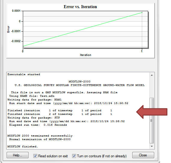
  1. Review the command line output from MODFLOW, and check to see where the issue began to arise. This will enable you to better pinpoint the cause of the error.
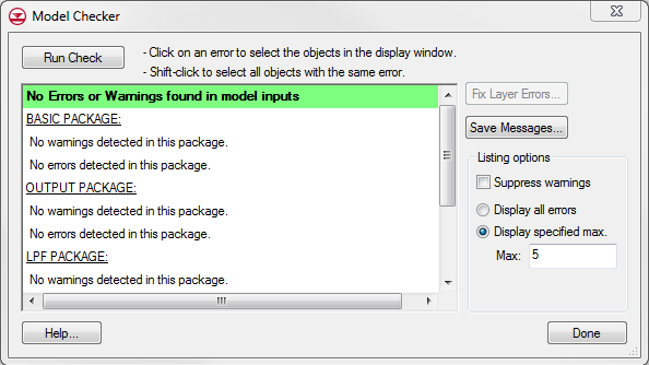
  2. Before running MODFLOW, make sure you always run the model checker to see if there are any errors that will prevent convergence. Immediately repair the errors found in the Model Checker. The Model Checker can be found by clicking MODFLOW | Check Simulation…
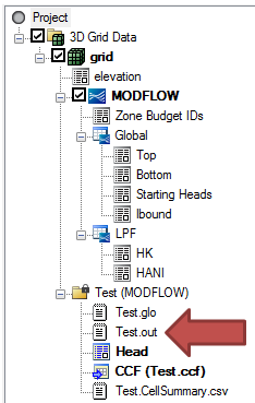
  3. Look in the MODFLOW output file (*.out) to search for missing values.

Further detail for some specific issues is also given below.

  • If the head is going to drop below the cell, use the MODFLOW-NWT solver.
  • Cells usually go dry due to a low recharge or a high conductivity. Adjust these parameters to better calibrate the model.
  • A transient water table will cause a fluctuation in the heads and the cells may go dry. In this case it is best to use the rewetting option which is available in all flow packages. However when possible MODFLOW-NWT is still the best solution to this problem.
  • Relax the maximum residual or head change criteria. It is best to not increase these values beyond about 1% of the value.

Hopefully with these troubleshooting tips, you can get your MODFLOW simulation up and running in no time. Additional information can be found in the Frequently Asked Questions section of the MODFLOW user manual under the question "My model hasn’t converged. What can I do?" If you are still struggling to get your model to work, consider using Aquaveo's consulting services for expert assistance.

Blog tags: