Aquaveo & Water Resources Engineering News

Troubleshooting MODFLOW, Part 2

A while back on this blog, we discussed troubleshooting MODFLOW errors. That blog post specifically discussed making use of the Model Checker, the MODFLOW command line output, and the output file. It also gave a few tips on how to fix your model when an error is encountered.

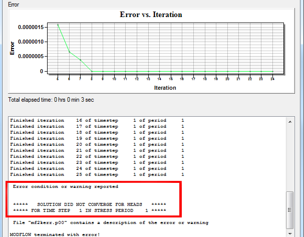
We wanted to expand on this, and specifically discuss what to do when you model doesn’t converge. When the model does not converge, an error message should appear in the MODFLOW command line output.

MODFLOW Not Converging

Essentially, when a model doesn’t converge a component of the model has not been setup correctly. This inaccurate component may only cause the model to not converge when certain conditions have been met, but otherwise the model will converge when those conditions are not present.

As for why your model converges sometimes and not others, there are a wide range of possible causes for instability. Here are a few general suggestions for helping MODFLOW converge:

  • Check model inputs for reasonableness.
  • Try running the model with different solvers. There are several solvers to choose from, and each of them have their own strengths and weaknesses. To switch solvers, select MODFLOW | Global Options | Packages and then select a different solver in the lower left area of the MODFLOW Packages dialog.
  • Try changing the solver parameters.
  • Check the troubleshooting items for a model that is not converging can be found under item K of the Frequently Asked Questions section of the Online Guide to MODFLOW.
  • Deselecting the "Enable saving of computed flows for all source/sink objects" option in the MODFLOW Output Control dialog.
  • Reduce the time step length for the model run.

It can take some time to review the model to discover why it is not converging, but the effort it worth it for an accurate result. For more in-depth assistance with model troubleshooting, please consider reaching out to Aquaveo’s consulting team.

Blog tags: 

Delineating a Floodplain Using a Scatter Point File

Looking for a quick way to delineate a floodplain in your area? WMS provides a way to delineate a floodplain and create a flood impact map quickly, using many different types of data. This blog post will cover how to delineate a floodplain using scatter point data.

Start by opening your scatter point data:

  1. Use the Flood | Read Stage File menu command to import your scatter point dataset. This is the recommended method for importing a scatter point set for using in delineating a floodplain.
Delineating the Floodplain
flood delineation

With the scatter point set imported, now delineate the floodplain.

  1. Select Flood | Delineate menu command.
  2. In the Floodplain Delineation dialog, choose the scatter point set you would like to model from the Select stage scatter point set drop-down menu.
  3. Select the specific dataset you would like to delineate from the Select stage data set drop-down menu.
  4. Set options for the Search radius, Flow path, and/or Quadrants depending on your individual model.
  5. When done with the Floodplain Delineation dialog, the delineation process will begin for the set of water surface elevations selected.

In order to create a flood impact map, it will be necessary to have at least two different delineations using varying datasets. If you wish to go on to create a flood impact map, repeat steps 1-5 with a different dataset to obtain a new floodplain delineation.

Creating a Flood Impact Map

WMS can use two separate floodplain delineations to generate a flood impact coverage. A flood impact coverage shows the difference between two flood depth or water level sets. The differences are divided into ranges or classes. Using the floodplains delineated in the previous steps, we’ll create a flood impact map. This can be used to compare how an area will react to a proposed levee for example.

  1. Select Flood | Conversion | Flood → Impact Map menu command.
  2. Choose the Original dataset based off your previous delineations.
  3. Choose your Modified dataset based off your previous delineations as well.
  4. Set the Increase and Decrease sections as desired.

Now that the flood impact map is created, you can use the Select Feature Polygon tool to double click on any of the polygons in the map. This will show you the Flood Extent Attributes dialog, which displays info such as the amount of change between the compared datasets as well as the impact class ID and name.

So this a brief overview of floodplain delineation from a scatter point file using WMS. Try it out in WMS today!

Blog tags: 

Converting Elevations to Depths

Have you ever found that the geometry data you’ve imported into your project is in elevation units, but the model you are using requires depth units? Using the the wrong topographic (elevation) or bathymetric (depth) data type can cause significant inaccuracies in your model results. It can also cause a lot of frustration. Therefore, it is always recommended to ensure you are using the correct data before running your model. SMS provides a way to change your data from elevation to depth (or vice versa) after it has been imported into your project.

Ideally, the correct bathymetry data will be used before assigning it to a geometry (2D Mesh, Cartesian Grid, etc.). When the original bathymetry dataset is incorrect, a new dataset should be created using the correct type (e.g., depth instead of elevation). The Data Calculator allows creating new datasets in SMS. This is done in the Scatter module by doing the following:

  1. Open the Dataset Toolbox
  2. Select the Data Calculator
  3. Select the scatter set
  4. Multiply the scatter set by -1
  5. Compute the new scatter set
  6. Use the new scatter set when generating the geometry
GSSHA

An elevation dataset can also be changed to a depth dataset with an existing geometry that has already been generated. This is done by doing the following:

  1. Open the Dataset Toolbox
  2. Select the Data Calculator
  3. Select the current elevation dataset and add it to the expression
  4. Multiply the dataset by -1
  5. Compute a new dataset

After creating the new elevation set, it needs to be designated as the elevation/depth for the geometry.

  1. Use the Data | Map Elevation command
  2. Select the new depth dataset

Now that you know how to change a dataset from elevation to depth, you can avoid the frustration of having the wrong data in your project. Try out the Data Calculator and other tools in SMS today!

Blog tags: 

Exporting and Importing to MODFLOW 6

In 2018, USGS released MODFLOW 6. This version of MODFLOW uses object-oriented programming to provide support for multiple models within the same simulation. Like many of you, we at Aquaveo were excited to see this new development and started on working on ways for GMS to interface with this new version of MODFLOW.

Did you know that with GMS 10.4 you can export your MODFLOW project for use with MODFLOW 6? This allows you to convert your older or current GMS projects for use with MODFLOW 6. This is just one of the new features in GMS 10.4.

Support has also been added to run MODFLOW 6 from GMS and read the head and flow outputs which may be contoured.

The general workflow process for saving, running, and importing the MODFLOW 6 files is as follows:

  1. After building your MODFLOW model, open the MODFLOW Global/Basic Package dialog.
  2. MODFLOW6
  3. In the dialog, turn on the Save MODFLOW 6 copy option under the MODFLOW Version section.
  4. Save your project.
  5. Open MODFLOW | Advanced | Run MODFLOW Dialog... to run the MODFLOW 6 files.
  6. Use the Custom MODFLOW option to point to the mf6.exe executable in program files (e.g., C:\Program Files\GMS 10.4 64-bit\models\mf6\mf6.exe).
  7. Browse to and select the NAM file out of the *_MODFLOW_mf6 folder that will have saved in the same directory as your GMS project. This is not the default, so you will need to browse for it at least the first time.
  8. Run MODFLOW.
  9. Use MODFLOW | Read Solution to select the MFN file out of the *_MODFLOW_mf6 folder.

The exported files can also be used directly in MODFLOW 6.

In the future, we plan to add more MODFLOW 6 functionality to GMS including a full interface. For now, get ready by converting your projects to MODFLOW 6 using GMS 10.4.

Blog tags: