Aquaveo & Water Resources Engineering News

Using Arc Annotations in SMS

Have you been wanting to have more contextual information for your arcs in SMS? Some projects require being able to easily tell which direction arcs are flowing or quickly see the distance of arcs. With the release of SMS 13.1, you may have noticed an addition to the display options that can help with this. The Arc Annotations options can provide additional contextual information to arcs in your SMS projects. This post will review how they can be accessed, and how they can help you while modeling in SMS.

The options for arc annotations are contained within the Map tab of the Display Options dialog. The Map tab can be accessed either by selecting Map from the list within Display Options, or by right-clicking on Map Data in the Project Explorer and selecting the Display Options… command. Once in the Map tab, the Annotations option can be turned on, which will then activate an Options… button. Clicking this button will bring up the Arc Annotation Options dialog where the new arc annotation options can be selected.

The main options that can be set here involve direction and ticks. Direction will show arrows on arcs to indicate which direction they are flowing. Ticks will show tick marks on arcs to indicate length measurements, which can help in visually seeing the real-world length of arcs. There are multiple options when it comes to how ticks will be displayed, giving you flexibility for your specific needs when it comes to modeling. It is important to note, however, that ticks will only display if the project units are set to feet or meters.
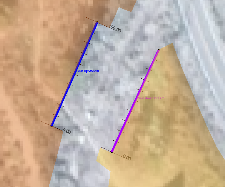
Example of the arc annotations

These features can be valuable in projects where the added visual cues and references can help with more instantaneously interpreting the graphical data. The customizability for tick display will also allow for the optimization of making this information look as presentable as possible within the model. For more details on the options available when using arc annotations, visit the XMS Wiki to learn more!

Try out using arc annotations in SMS 13.1 today!
Blog tags: 

New Features in GMS 10.6 Beta

Aquaveo is pleased to announce the release of the Groundwater Modeling System version 10.6 in beta! With this beta release, GMS contains changes and improvements to various features, much of it involving increased support for MODFLOW 6 functionality. We’d like to highlight some of the new functionality you can expect to find in GMS 10.6 beta.

Transport Support for MODFLOW 6

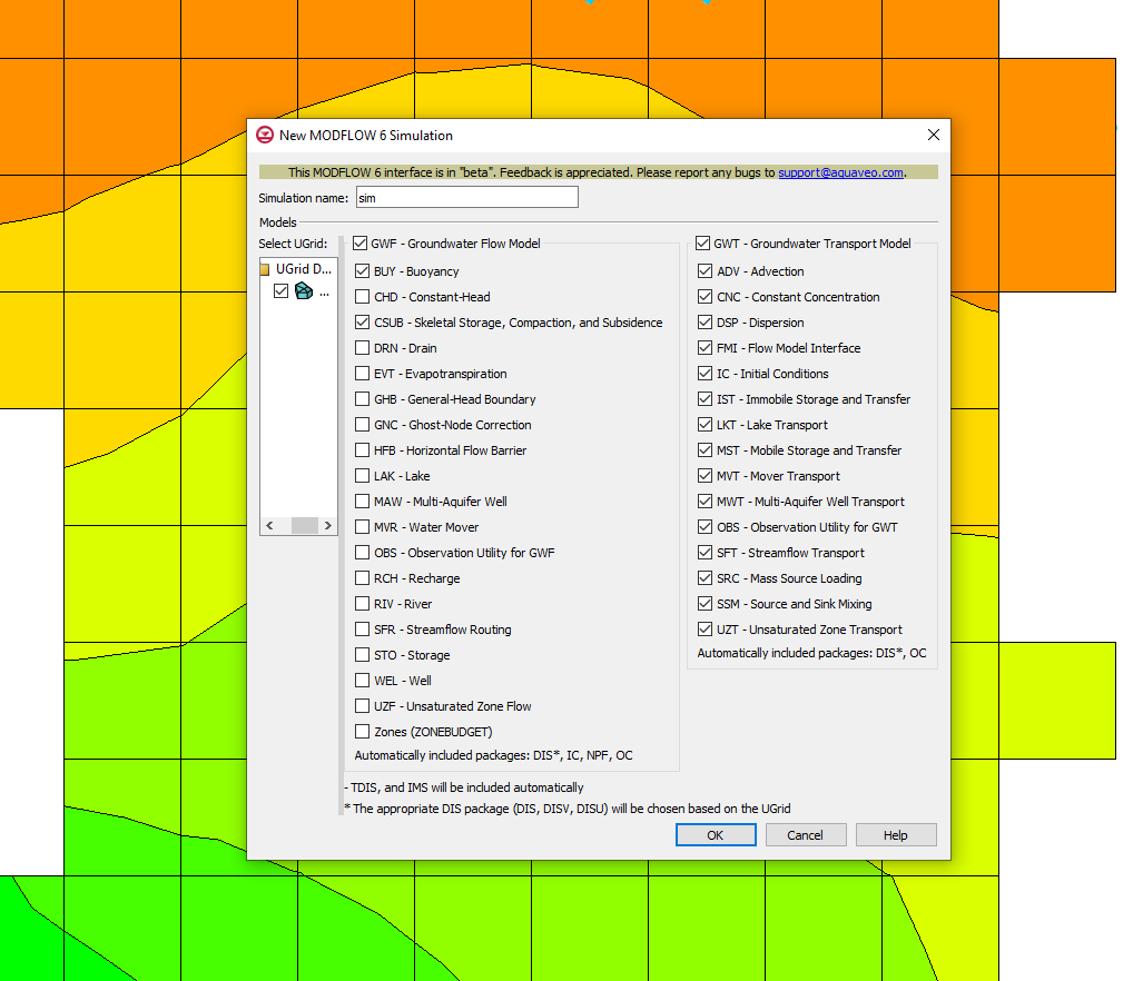
GMS 10.6 beta adds the ability to work with transient models for MODFLOW 6, as demonstrated by the addition of transport packages relevant to the GWT (Groundwater Transport Model) package. These will be helpful to many different aspects of groundwater transport modeling, such as dealing with advection, constant concentration, and dispersion. With the wealth of packages this alone adds to GMS 10.6 beta, it will add a lot of functionality to what GMS can do with MODFLOW 6 simulations.

Example of the new MODFLOW 6 Simulation dialog
Increased GWF Package Support MODFLOW 6

In addition to the suite of transport-related packages that GMS 10.6 adds to work with, support has also been added for more packages relevant to the GWF (Groundwater Flow Model) package. In this case, this includes the addition of the BUY (Buoyancy) and CSUB (Skeletal Storage, Compaction, and Subsidence) packages. The addition of these packages will help flesh out what GMS 10.6 beta can do with MODFLOW 6 simulations.

Support for Exchanges in MODFLOW 6

Support has also been added in GMS 10.6 for exchanges. These include the GWF-GWF and GWF-GWT exchanges. These can be used to help different models in a GMS project interact, and designate the nature of how they should interact. GWF-GWF exchanges can help two different GWF models interact together and hydraulically connect, telling each model that there is flow along a shared edge. GWF-GWT exchanges can help designate which GWF and GWT models should interact with each other.

These are just a few of the new features and changes coming out as part of the release of GMS 10.6 beta. You can find more information on what will be introduced in GMS 10.6 beta by going to the Aquaveo XMS Wiki. Try out these features and more by downloading GMS 10.6 beta today!

Blog tags: 

Making Use of WMS Contour Labels

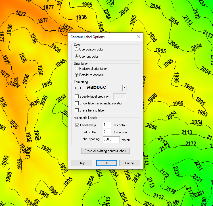
Does your watershed project need to display contour elevations values? WMS (as well as SMS and GMS) have the ability to use contour labels to help determine elevation levels at a glance, which can be very helpful for many projects, especially when modeling drainage. This post will review the different ways that contour labels can be utilized within WMS.

Example of contour labels

There are essentially two different forms or methods when it comes to applying contour labels to contours when working in WMS: manual and automatic. In both cases, the way contour labels are displayed can be modified in the Contour Label Options dialog, which can be accessed by clicking the Label Options… button when the Contour Options dialog has been brought up. Here there are options for color, orientation, font, scientific precision, etc. There is also a button to "Erase all existing contour labels" and start over from the beginning.

The manual method consists of using the Place contour label tool to click on contours and manually assign contour labels to the positions the user chooses. This option is only available in certain modules, such as 2-D Grid and Terrain Data. Note that these may disappear when options in the Contour Label Options dialog are modified, so it may be best to determine the contour options before you manually place contour labels. Labels can also disappear when contouring options are changed, when the Graphics Window is refreshed, or can even be manually deleted when holding down Shift and clicking on a label with this tool active.

The automatic method consists of using the Automatic Labels section in the Contour Label Options dialog to automatically populate labels along the contours. When activated, this allows you to set how many of the contours should be labeled, which contour to start with, and how far apart the labels are spaced out. Unlike in the manual method, changing options for these labels should not delete them, as they should automatically repopulate based on current settings when the OK button is clicked to close the Contour Label Options dialog.

While every project will be different, when using contour labels, some recommended settings to start off with would be to use "Color Fill and Linear" as the Contour Method, and to automatically space out labels. This way more discrete contours as well as gradient values can be easily displayed and it will be easy to determine at any given location what the elevation is. Also recommended is to avoid using white text in most instances, as it is usually difficult to read, except perhaps in instances where color fill is used.

Try out experimenting with contour labels in WMS 11.1 today!

Blog tags: 

Best Practices for Extracting Features

Have you used the Extract Features tool in SMS before? The Extract Feature tool lets you generate channel and bank arcs from elevation data. There are some tricks to optimizing the use of this tool. This post will review some of the best practices that you should follow when you extract features from elevation data in SMS.

Digital Dams
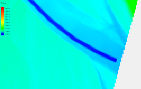
Example of a digital dam

These are often artifacts from stamping channels or unprocessed LIDAR data and they can cause problems determining flow directions on the raster. The pre-processing engines (TOPAZ and TauDEM) fill these prior to computing flow directions, which can be a problem if the centerline strays from the thalweg and matching depth is computed off of the filled raster and not the original, which will also cause higher elevations along the channel above the dam. These can be fixed by either:

  • Trimming the raster above the dam by right-clicking on the raster and selecting Convert To | Trimmed Raster using a Map Module polygon.
  • Modifying elevations downstream of the dam to match correct stream thalweg elevations by right-clicking the raster and selecting Editing | Edit Raster using selected arc elevations.
Placing Points for Extracting Bank Features

When extracting bank features, place the point closest to the most important area. For example, if a section is being used for bridge analysis, place the point close to the bridge. This allows the bank lines to stay the closest to the original feature. If the Extract Bank tool misses a bank section, try moving the point to the missed section and run it again.

Extracting Centerlines for Braided Streams

When extracting centerlines for braided streams, sometimes they may not follow the actual stream location because of digital elevation model inaccuracies. When this happens, extract both centerlines and manually merge the arcs into a single arc after both centerlines have been extracted.

Use the Depth That Is Option

The following guidelines should be observed when using the "Use the depth that is" option:

  • If there is a single well-defined channel with a strong bank feature, use the "Closest to centerline" option.
  • If there are multiple floodplain bank features, use the "Closest to previous" option, otherwise, the Extract Features tool may catch a different floodplain feature.
  • If there are multiple channels or a braided stream (and you want to catch the widest extents of the channel), use the "Furthest from centerline" option.

Try out some of these best practices while extracting features in SMS 13.1 today!

Blog tags: