Aquaveo & Water Resources Engineering News

Using the ADCIRC Levee Elevation Tools

Have you needed a way to quickly fix a levee structure in your 2D mesh for your ADCIRC model? The SMS toolbox has tools devoted to helping you develop ADCIRC models that accurately reflect levee elevations. That’s our focus in today's blog post.

The elevations on your levee can affect the outcome of your ADCIRC model. What's more, having the wrong levee elevations can even cause your ADCIRC model to fail its run. But the Check/Fix Levee Crest Elevations tool and the Check/Fix Levee Ground Elevations tool are designed to help mitigate this issue. These tools ensure that the elevations both on the ground and on the crest of your ADCIRC levee feature match the desired measurements.

For example, an ADCIRC model run can fail because the levee ground elevation is higher than the levee crest elevation. The Check/Fix Levee Ground Elevations tool checks the ADCIRC domain elevation against the boundary condition coverage that defines the levees. Then, if adjustments are required, the Check/Fix Levee Ground Elevations tool creates a new dataset that can be mapped as the elevation for the 2D mesh.

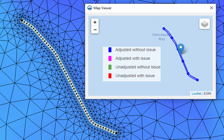
On the other side of things, the Check/Fix Levee Crest Elevations tool can help ensure that the crest of the levee in the model does not go above or below the known measurements for the levee crest. A check line is either created in a coverage or imported into SMS then converted to a coverage. The check line has levee crest elevation information against which the Z values of the levee arcs get checked. If the levee crest elevations vary too much from the check line’s elevations, then the Check/Fix Levee Crest Elevations tool adjusts the z values on the levee arcs to match the check line.

Example of the ADCIRC Check/Fix Levee Crest Elevations tool

In short, the Check/Fix Levee Crest Elevations and the Check/Fix Levee Ground Elevations tool can facilitate your modeling of ADCIRC levee features.

Try out these new levee elevation tools in SMS today!

Blog tags: 

Using a 2D UGrid with SRH-2D

A 2D mesh in SMS has long been the standard geometry for SRH-2D simulations. However, you might have noticed in more recent versions of SMS that SRH-2D simulations can also use 2D unstructured grids (UGrids). Today, we examine what using a 2D UGrid can mean for SMS users who model SRH-2D simulations.

Being able to use a UGrid offers a couple advantages. For one, 2D UGrids don't require the SRH-2D Post-Processor because, unlike 2D meshes, they are already centroid-based. This means the SRH-2D results can be read directly onto the 2D UGrid. Additionally, the same SRH-2D model can be run with a mesh and then run with a 2D UGrid. Since the two geometries differ in how they store data, this practice might be helpful in troubleshooting issues with the geometry design for your model. In most cases where the mesh is well built, there should not be significant differences between the results you get from a UGrid-based SRH-2D simulation and a mesh-based simulation.

The steps for creating a 2D UGrid for an SRH-2D simulation are essentially the same as creating a 2D mesh:

  1. Build a mesh generation coverage with polygons.
  2. Specify what kind of grid-like structure you want in each.
  3. Instead of converting the coverage to a 2D mesh, convert it to a 2D UGrid.

An already-existing 2D mesh can also be converted to a 2D UGrid if so desired.

Example of the 2D Mesh Polygon Properties dialog being used for UGrid or mesh generation

It's important to note that there are not yet any manual tools for editing 2D UGrids, so any desired adjustments to a 2D UGrid should be made before the UGrid is generated. As with the 2D mesh, this can be done by double-clicking in the polygons in the mesh generation coverage and using the dialogs that appear.

Furthermore, the principles for creating a quality mesh apply to creating a quality 2D UGrid. The quality of a UGrid is just as important to the model outcome as the quality of a mesh. In 2D UGrids for SRH-2D simulations, please keep in mind the following:

  • The elements should transition gradually from large to small and vice versa. Adjacent elements should not have enormous variations in size.
  • Areas that need more refined results should have finer quality elements.
  • For areas that use the patch option, the elements should be fairly even.
  • Triangular elements should not be excessively narrow.

These are only some of the considerations.

Much of this can be avoided by making sure that the mesh generator coverage is designed correctly. Again, adjustments to the 2D UGrid can really only be made in the mesh generator coverage before the UGrid has actually been generated.

Try using 2D UGrids in an SRH-2D simulation in SMS today!

Blog tags: 

New Features in GMS 10.7 Beta

We are pleased to announce that GMS 10.7 has been released in beta. In order to improve your groundwater modeling projects, we’ve included many new features into GMS 10.7. Here are a few of the new features we are excited about.

Animation Tools Allow Exporting in MP4 File Formats

GMS 10.7 has been improved to allow you to save your animation files in the MP4 format. This will enable you to open animation files outside GMS and view the animation created before returning to GMS. An MP4 file is a common animation file that allows you to open the animation in a number of different player applications.

Introduction of the New Toolbox Features
Example of the Toolbox in GMS 10.7

GMS has added a new Toolbox feature. This Toolbox contains many different tools for completing common calculations and functions in GMS. For example, the new Toolbox contains a tool for merging datasets and another tool for converting geometries to an unstructured grid. We have provided dozens of tools in the Toolbox to work with a wide range of data, so we recommend looking through the available tools to see what would be of most use for your projects.

Many of the tools in the Toolbox can be used instead of using the Data Calculator. This shortcuts some of the processes to help you build your groundwater model faster. Additional tools will be added in future versions of GMS. If you have a common process that you would like to see added as a new tool in the Toolbox, please let us know.

Updated MDT Package for MODFLOW 6

In MODFLOW 6 has updated the MDT package. The MDT package allows for matrix delineation transport as well as shifting matrix delineation start time. Improvements have been made to how this package works with MODFLOW 6 in GMS.

These are just a few of the features that are a part of GMS 10.7 beta. Try out these features and more by downloading GMS 10.7 Beta today!

Blog tags: 

Trimming DEMs in WMS

Have you imported a DEM into WMS but wanted to trim it down to use only a part of the original data? WMS has tools designed to help you trim DEMs that you have imported into WMS, so you can use only the part of the data that's relevant to your model. In this article, we explore the ways that this can be done in WMS.

Trimming a DEM can help eliminate extra data that is not necessary for your project. Having a DEM that is too large or contains data that is irrelevant to your project can cause your project to operate slower and in some cases can skew the results of your project.

One option for trimming a DEM is when it's part of the GIS Data Module as a raster. To do this, draw a feature object polygon in a map coverage then select it. With the polygon selected, you can right-click on the raster and select the Convert To | Trimmed Raster command. This trims the raster along the border of the polygon. The trimmed raster can be converted, if desired, to a DEM that will show up under the Terrain Data folder.

Of course, there are also tools for trimming files that are already in the Terrain Data Module as DEMs. These tools can be accessed either through the DEM menu when in the Terrain Data Module or through the right-click menu for a DEM item in the Project Explorer. In both places, the tools are found in the Trim submenu.

There are two ways to trim DEMs in the Terrain Data Module: by elevation and by polygon.

When trimming a DEM by elevation, WMS brings up a dialog that lets you specify the maximum elevation that you want the DEM trimmed to. The newly created DEM will have only elevations up to the maximum elevation set in this dialog. The contours will likely change to represent the new range of values in the trimmed DEM.

Example of trimming a DEM using a polygon in WMS

When trimming a DEM using a polygon, the program turns the mouse into a tool to click out the polygon in the Graphics Window. To finish the polygon, double-click where the last point is desired. Once the polygon is complete, the trimmed DEM is automatically created.

Note that a DEM created this way is still a rectangle. This is part of the definition of a DEM. However, only the points inside the drawn polygon will be active, so the displayed contours will end at the borders of the polygon you drew. The points that were outside the drawn polygon, which make up the rest of the bounding rectangle, are set to NODATA.

Take advantage of DEM trimming tools in WMS today!

Blog tags: