Aquaveo & Water Resources Engineering News

Changing an Existing Model to be a Predictive Model

When you have a completed GMS model, you can use that same model to create a predictive model. A predictive model is used to make predictions based on hypothetical future scenarios. For example, you may need to create a model that predicts if an aquifer will experience strain with an increased population drawing from the aquifer in the model area.
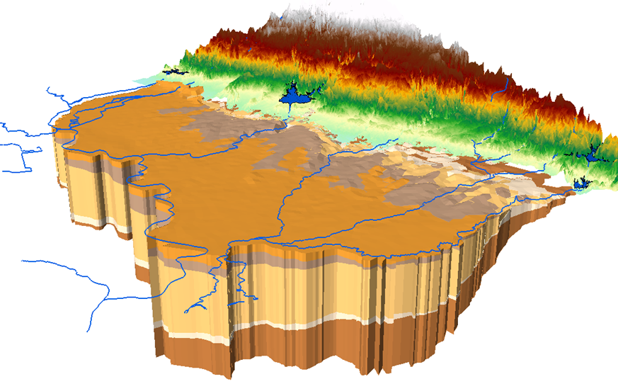
Groundwater model

In general, a predictive model is created by using an existing model, then altering an aspect of that model based on the hypothesis. You then run the model again and compare your results with your prediction. Any version of MODFLOW, or any of the other available numeric models in GMS, can be used to create a predictive model.

One method of setting up a predictive model might be as follows:

  1. Create and run a steady state model
  2. Calibrate the model to reduce error in the predictive model
  3. Set the transient settings to a future date
  4. Run the transient model

It is important for you to have an expectation of the outcome of the model run so that you can compare the results with that expectation. When the model run is completed, carefully review the model run results to determine the accuracy of the predictions. When creating a predictive model, you can make use of stochastic analyses.

If the predictive model seems to be far outside of your expectations, then you will need to troubleshoot the existing model before running the predictive model. Using a poorly developed existing model often leads to issues in the predictive model. Make certain the existing model has been well calibrated to closely match the field-observed values. If possible, calibrate the existing model to multiple sets of observation data before creating a predictive model.

Now that you know some of the principles in developing a predictive model, creating your own predictive model in GMS today!
Blog tags: 

Tips for Managing Cross Sections in WMS

Cross sections are commonly used in 1D models within WMS. Here we discuss a few things to help you better model using cross sections.

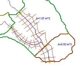
When you create cross sections in WMS, you must create them on "1D-Hyd Cross Section" coverage. You then create the arcs on this coverage to represent the cross sections.There are a few things you should remember when setting up your cross sections:

  • Cross sections should be located at fairly frequent intervals along the river. This makes sure the characterization of the stream channel and floodplain flow and capacity is accurate, which gives you better results.
  • You should place cross sections especially at locations of significant change, where levees begin and end, at hydraulic structures, and around stream junctions.
  • The cross section arcs should generally stretch from one side of the river floodplain to the other.
  • They should be generally perpendicular to the river arc where they cross.
  • Cross section arcs should not cross each other.
Hydraulic Model Example with Cross Sections

In addition to the above, each cross section should have the following required information:

  • River name
  • Reach name
  • River station
  • Description
  • Station–elevation data
  • Downstream reach lengths
  • Manning’s n values
  • Main channel bank stations
  • Contraction and expansion coefficients

It is recommended that the station number be visible on the map view to make the cross sections more identifiable. This can be enabled in the Display Options dialog. When numbering stations, they must be in ascending numerical order from downstream to upstream. If changes are made, be sure to renumber the stations.

Converting an arc into a cross section arc can be done automatically or manually. You can automatically do it by taking the following steps:

  1. Define or import a TIN.
  2. Create an area property coverage, a centerline coverage, and a 1D-Hyd cross section coverage.
  3. Use the Extract Cross Section command to extrude the cross sections from the 2D arcs.

To manually create a cross section arc:

  1. Double-click on the cross section arc and select Assign Cross Section.
  2. Define the various elevations and data as desired.

Try out these tips and procedures today in the WMS Community Edition!

Blog tags: 

Using Internal Sinks and Links in SRH-2D

Do you have an SRH-2D project that requires placing a drain inside the mesh? Or perhaps you have two seperate meshes in your project where you need to have water flowing between them? Both of these scenarios can be resolved by respectively using the internal sink and link boundary conditions.

Internal Sink Boundary Condition

The internal sink boundary condition is assigned to an arc on an SRH-2D boundary condition map coverage. Unlike an inflow or outflow boundary condition, an internal sink is assigned to an arc that is inside the mesh boundaries.

An internal sink can simulate wells, drains or other points of outflow. It can also simulate a source by specifying a negative number for the flow.

It should be noted that an internal sink boundary condition should not be used as a model’s primary source of inflow or outflow. Inflow and outflow boundary conditions should be placed on the mesh boundary.

Links

Link boundary conditions can be used to simulate moving water between two different meshes or two different areas of the same mesh. Links can sometimes be used to make a simple representation of a pipe or similar structure connecting two areas.

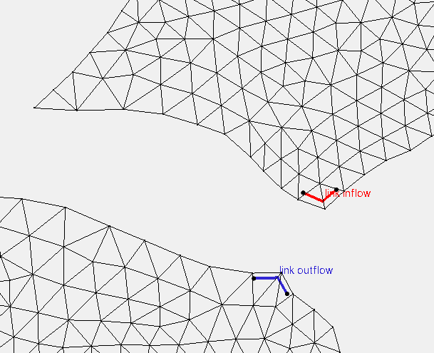
Links are made by making two arcs on an SRH-2D boundary condition coverage. Both arcs are selected when assigning the Link property type. One arc should be assigned as the link inflow boundary condition and the other arcs should be assigned as the link outflow.

Example of an link boundary conditions

It should be noted that link boundary conditions should not be used to model culverts or other such structures. Also, link boundary conditions should not be used as the primary inflow or outflow source for a project.

Now that you know a little more about using internal sink and link boundary conditions, try using them in your SRH-2D projects in SMS.

Blog tags: 

Using MODFLOW Native Files

If you have been using MODFLOW with GMS for any amount of time, you have likely noticed that GMS uses a modified version of the MODFLOW files. This is so that the MODFLOW files can be used more efficiently by the GMS interface.

However, there are times when a project may require using the native MODFLOW files. This is often necessary when opening a MODFLOW project that was not originally created in GMS, or when sharing a project with someone who does not have access to GMS.

When importing native MODFLOW files into GMS, there are some important concepts to keep in mind:

  • You will need to start by importing either the NAM file or MFN file. These files contain a directory for the other files in the MODFLOW project and how they should be opened.
  • It is important to keep all of the MODFLOW files together in the same directory. Having only the NAME or MFN file will not be enough to open the MODLOW project.
  • Files for the packages used with the project will typically have a file extension that matches the package. For example, the Wells package will have the extension "*.wel".
  • All native MODFLOW files can be opened and reviewed using a text editor if needed. See the MODFLOW user guide for information on the file format.
The Save Native Text Copy option

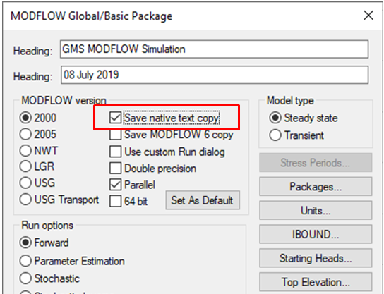
Native MODFLOW files can be exported from GMS by turning on the Save Native Text Copy option in the MODFLOW Global/Basic Package dialog. When exporting native MODFLOW files, keep the following in mind:

  • GMS will create a separate directory with the native MODFLOW files. This directory will typically be the project name with "_text" appended to it. For example, if the project is named "Aquifer", the directory will be named "Aquifer_text".
  • All files in this directory should be kept together.
  • As mentioned before, the files can be reviewed using a text editor.

With GMS 10.4, MODFLOW 6 native files can be imported and exported.

Being able to use native MODFLOW files can greatly enhance collaboration with projects. Try out importing and exporting native MODFLOW files in GMS today!

Blog tags: 

Obtaining Nonstandard Data for Curve Numbers

Calculating curve numbers is a necessary process for many WMS projects. WMS contains a number of tables with suggested soil and land use data for use in calculating the curve number. These are not comprehensive lists of every possible soil data resource, however. These are, only those that are readily downloadable through WMS.

So what do you do if you need to use soil or land use data from a location without data readily available in WMS? You can use nonstandard soil or land use data by creating a file with the data formatted as a table. The format of those land table files can be applied to create a table for any soil data source, such as local shapefiles developed for specific projects.

Example of a land use shapefile

The format for these files is a set of columns as follows:

  1. Soil ID number
  2. Category Label
  3. Hydrologic soil group A
  4. Hydrologic soil group B
  5. Hydrologic soil group C
  6. Hydrologic soil group D

Once you have created a text file with your soil or land use data, import it into WMS as you would any other soil or land use data.

If you’re building your own table for your soil data, there are sources for the tables and charts to help facilitate estimating the curve numbers to put into the table.

For an explanation of or introduction to SCS or runoff curve numbers, a good source is the National Conservation District Employees Association. Their guidance may help clarify the process of creating your own curve numbers.

Additional sources can also be found for soil or land use data. Use whichever data source you feel is appropriate for your project. As long as the data is formatted correctly, WMS should be able to import it.

Try out importing soil and land use data from locations around the world using WMS today!

Blog tags: