Aquaveo & Water Resources Engineering News

Changing Ports for Aquaveo Licenses

Sometimes it may be beneficial to change the license location for one or more of our XMS (GMS, SMS, and WMS) software on your computer. There are a number of reasons to do this, including to increase security and flexibility. The port number has to be changed in two locations for the port to be switched over properly.

First, open the Aquaveo License Registration dialog. This dialog comes up when you first download the software so you can enter the licensing information. If you've already done this, the dialog can also be accessed by selecting Register… under the Help menu. After opening Aquaveo License Registration, do this to change the port number:

  1. Select the Advanced Options… button.
  2. At the top of the dialog, click the Change Location… button.

A dialog labeled Aquaveo License Registration – Change License Location will open. This dialog shows the IP address that is currently being used, as well as the current port number. This is where you can change the port number.

Changing XMS Port License

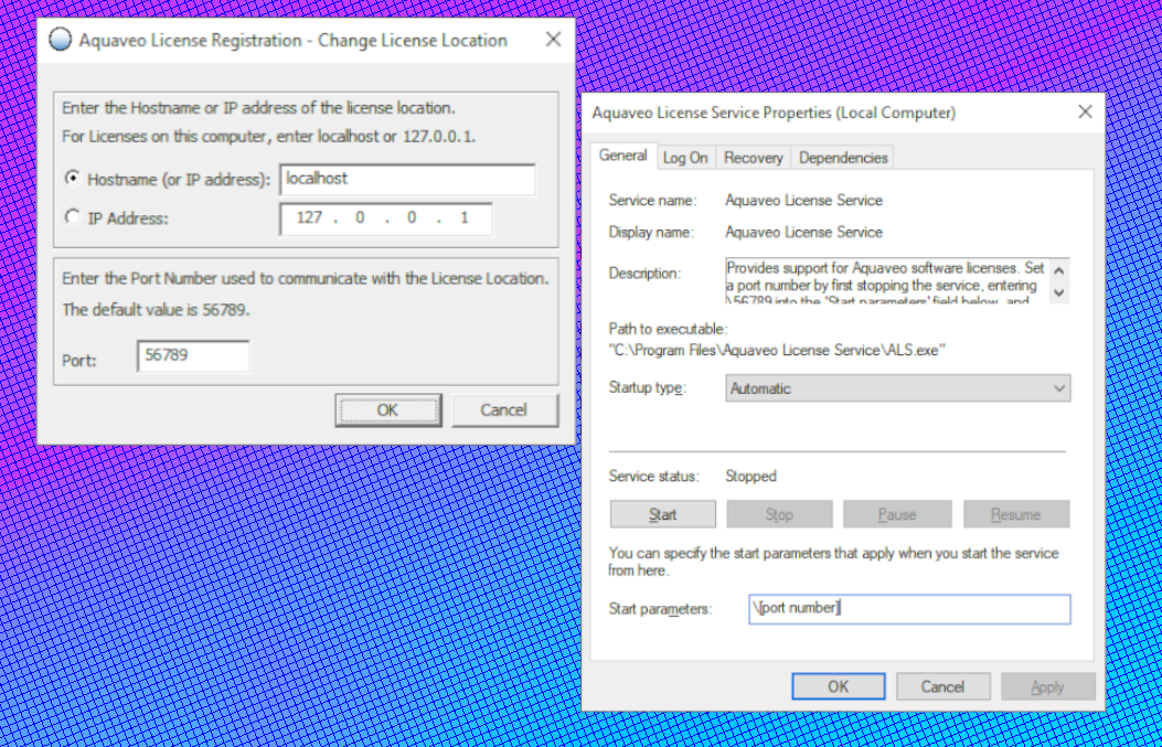
The other location the port number needs to be changed In order to switch over properly is the Aquaveo License Service Properties. Follow these instructions to open ALS Properties:

  1. Open the Services app. This can be found by typing "services" into the search on your taskbar.
  2. In the list of services, find "Aquaveo License Service" and select Properties.
  3. On the General tab at the bottom click Stop.
  4. In the Start Parameters, type the new port number with a backslash (\) in front of it.
  5. When you are finished, click Start.

The port location change won’t be complete until the port number is changed in both the Aquaveo License Registration and the Aquaveo License Service Properties.

Open any of the XMS software and check out how you can change the license location today! If you have more questions about licensing, contact our Licensing Support by emailing licensing@aquaveo.com.

Blog tags: 

Speed Up Edits Using Mesh Subsets

While working with meshes in the Surface-water Modeling System (SMS), you may have noticed that the more elements there are in the mesh, the slower the processing speed gets when making edits. Subset edit mode allows you to edit just one portion of the mesh at a time, which can increase the processing speed considerably. You can access the “Edit Subset” option by selecting the elements on the mesh you want to work with and right-clicking in the Graphics Window.

Using the Edit Subsit mode

Working within the edit subset mode was designed to let you work on a large mesh without overtaxing your machine’s memory and processing power. When you select a section of the mesh and enter subset mode, SMS will stop displaying the parts of the mesh that were not selected. This allows SMS to ignore the elements and data on the parts of the mesh outside of the subset. This can help free up computing power while making changes to the subset mesh. When you are done making your changes, you can exit the subset mode to have SMS include your changes in the full-sized mesh.

While in subset mode, the mesh in the Project Explorer will be tagged with the (subset) suffix. Some of the specific commands that you can use in subset edit mode are:

  • Commit Subset: this command takes you out of subset edit mode, and merges the changes made to the mesh subset with the rest of the mesh.
  • Revert Subset: this command takes you out of subset edit mode, but does not retain any of the changes made to the mesh subset.

You may notice that "Refine" is listed as an option in the right-click menu while subset edit mode is active, however you are not able to refine elements in a subset. If you select "Refine" an error will appear stating "Command not available in subset edit mode."

Some actions that you are not able to perform while in subset edit mode are:

  • Making changes on the border of the mesh subset.
  • Creating a new mesh.
  • Running a numerical model.
  • Changing attributes such as boundary conditions on nodes, nodestrings, and elements.
  • Renumbering node/nodestring/element IDs.

Head over to SMS and see how subset edit mode speeds up the processing time when editing large meshes today!

Blog tags: 

Utilizing the Transient Step Function Method

The Groundwater Modeling System (GMS) provides tools for working with transient MODFLOW simulations. When working with transient dataM in a MODFLOW model, it is important to understand stress periods and how GMS calculates their values. There are two different methods you can use to define the values for a stress period: the continuous time series method, and the step function method. This blog post will cover how to input the data for a stress period in the XY Series dialog so that GMS will calculate their values correctly.

Transient MODFLOW simulations use time intervals called stress periods to define the values of transient stresses such as pumping rates, and river stages. The values for stress periods are entered in the XY Series dialog, which is opened from the Attribute Table dialog. For a continuous time series, you need to enter only one data point per time step. When you enter only one value per time step, GMS assumes that the value continues to increase through the stress period, creating a straight line connecting the two points for a smooth transition. But because GMS needs a constant value for each stress period, it will take an average of the starting values of that particular stress period and the starting value of the following stress period.

The step function method tells GMS that there is only one value for each stress period, rather than a continuously increasing value. To input data in the XY Series dialog so that GMS knows that there is only one constant value through the entire stress period, you’ll need to enter both a start value and an end value. The figure below shows an example of the format to use.

Step function in GMS

As you can see in the above figure, you need the end value of a stress period to match the start value of the following stress period. This creates "steps" in the data, telling GMS to read a constant value through the entire stress period, rather than having a gradual increase from beginning to end.

Head over to GMS and try creating a step function for your transient MODFLOW model today!

Blog tags: 

Creating Reliable Arc Pairs for SRH-2D

SRH-2D models in the Surface-water Modeling System (SMS) often use pairs of arcs to represent structures like culverts, weirs, bridges, and gates. For some projects, it matters for SRH-2D about how these arc pairs are drawn, and improperly drawn arcs can stand in the way between you and a successfully run model.

Arc pairs in SRH-2D models need to be drawn from left to right as if you are looking from upstream to downstream. This can get quite confusing, so here are a few tips for how to be able to tell which direction your arcs need to go by making use of display settings in the Display Options dialog.

Using vectors to find stream direction

If you’re not sure which direction is upstream and which is downstream, select 2D Mesh from the list on the left of the Display Options dialog and turn on Vectors. This requires having a dataset associated with the mesh that contains vector values. The vectors will display the direction the water is flowing, which makes it easy to be able to tell where upstream is. Now, to draw the arcs in the correct direction, imagine you are standing upstream and looking downstream. Then start the arc on your left and end it on your right. Both arcs need to be drawn in the same direction.

What do you do if you’ve already drawn the arcs and then you try to run your simulation and it fails? If the failure is caused by misdrawn arcs, the error will read "Program stopped due to the following: Linked Pair nodestring direction is wrong; please reverse them". The fix is simple if you have only one pair of arcs on your mesh: select both arcs in the Graphics Window, right-click, and select Reverse Arc Direction.

The Reverse Arc Direction command

However, the existence of more than one arc pair can make solving this error a little more complicated. Rather than going around and either redrawing or reversing all the arcs, here's what you can do to pinpoint the problematic pair. First, open the Display Options dialog. On the Map tab check the box next to Annotations and click the Options button. In the Arc Annotation Options dialog, turn on Show arc direction arrow. Doing this will add arrows to the arc, pointing toward the end. This makes it easy to look at the arcs and see which ones are facing the wrong direction, at which point you can use the same steps as above to reverse the arc direction.

Head over to SMS and use this guide to help your SRH-2D model run more smoothly today!

Blog tags: