Aquaveo & Water Resources Engineering News

New MODFLOW-USG 3D Dataset to Array

While most groundwater projects typically only need a 2D dataset to define arrays, 3D datasets are becoming more available. There’s a new feature in the Ground-water Modeling System (GMS) version 10.8 for MODFLOW-USG and MODFLOW-USG Transport models. MODFLOW-USG and MODFLOW-USG Transport are MODFLOW models that were designed specifically to be used with unstructured grids, or UGrids. The Recharge (RCH), Evapotranspiration (EVT), and EvapoTranspiration Segments (ETS) packages in MODFLOW-USG now have the option to use a 3D dataset to define the input arrays. Previous versions of GMS only had the option to use a 2D dataset with a matching 2D structured grid.

Example of the 3D Dataset to Array option

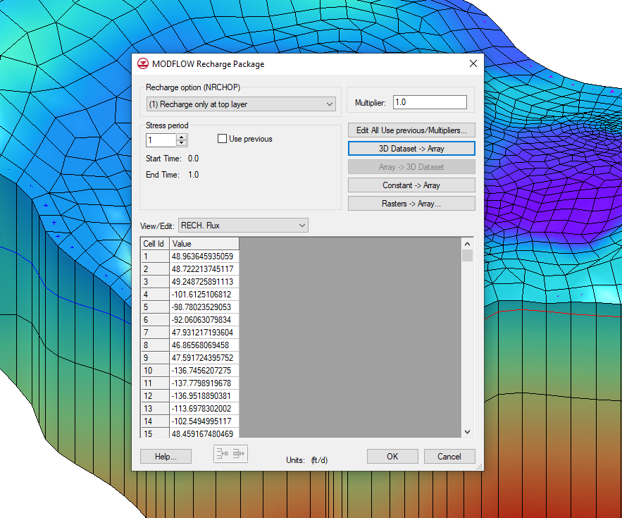
You can find the 3D Dataset → Array button in the properties dialog of the Recharge (RCH), Evapotranspiration (EVT), or EvapoTranspiration Segments (ETS) package. In order to use the 3D Dataset → Array button, the 3D dataset in the MODFLOW-USG model has to have the same number of rows and columns as the 3D grid. If the rows and columns don’t match the 3D grid, then the button will be grayed out and you won’t be able to use it.

Clicking the 3D Dataset → Array button will bring up a Select Dataset dialog with a list of all the datasets associated with the current 3D grid. You can then select the relevant dataset to assign values to the MODFLOW-USG package. 3D datasets are often created using the 3D Scatter Point tool, which can help you interpolate rainfall data to the cells on your grid. If you are using a transient dataset, then the dataset values will be interpolated linearly to each stress period when they are copied to the array. You can learn more about using the 3D Scatter Point tool on this page of our wiki.

Now head over to GMS 10.8 and try using the new 3D Dataset → Array button in your MODFLOW-USG or MODFLOW-USG Transport project today!

Blog tags: 

Differences Between AHGW and AHGW Pro

The Arc Hydro Groundwater tools developed by Aquaveo help you manage groundwater and subsurface data within ArcGIS. When ESRI released ArcGIS Pro as the successor to the ArcGIS Desktop applications, we made some changes to the AHGW tools to adapt to the interface of the new ArcGIS application. Today we’ll talk about some of the differences you should expect when making the switch to AHGW Pro. If you're curious about ArcGIS Pro in general, you can follow this link to learn more about it.

Example of the AHGW Pro ribbon

One of the major visual differences between AHGW in ArcGIS Desktop and ArcGIS Pro is the location of the tools. All the AHGW tools in ArcGIS Desktop are located on an AHGW toolbar that can be either docked or floating. In ArcGIS Pro, the AHGW toolbar has been replaced with an AHGW Pro ribbon which includes only some of the tools that were on the old AHGW toolbar. The rest of the subsurface and groundwater analyst tools are imported as a python toolbox. Additionally, AHGW wizards have been converted to panes, which contain all pages of the wizard.

Some of the tools that were previously available in the AHGW desktop applications are not available in AHGW Pro. Some of these tools will be included in upcoming iterations of AHGW, but there are some that will get left behind. Most notably, we have no plans to include any of the AHGW MODFLOW analyst tools in ArcGIS Pro. You may also notice that other file import and export options have been removed.

We made functional changes to some of the AHGW tools in ArcGIS Pro as well. AHGW Pro has moved away from using raster catalogs, using mosaic datasets instread. This may be a little confusing at first, as the tools still have "raster" in the name. Just know that when it says raster, it means mosaic dataset. There are lots of tools that can help you create and modify mosaic datasets inside of ArcGIS Pro, which you can easily find just by typing "mosaic dataset" in the search bar at the top of the window.

Go to ArcGIS Pro and check out the new AHGW Pro tools today!

Blog tags: 

Using the Mask Subset Smoothing Option

The Surface-water Modeling System now includes two new tools in the toolbox to help you when your project requires any amount of dataset smoothing. Previous versions of SMS had you use the Dataset Toolbox to smooth a dataset. These new tools can do everything that the Dataset Toolbox used to do, and more.

Both the Smooth Datasets and Smooth Datasets by Neighbor tools are used to eliminate extreme slopes in a dataset, but they require different inputs, which will tell SMS how to incorporate the relationship between nodes. The Smooth Datasets tool uses an anchor and either an elemental area change or maximum slope for its calculations. Smooth Datasets by Neighbor uses the relationship between neighboring nodes and a selected interpolation method: average or inverse distance weighted. Note that the current version of these tools are designed to be used on node-based datasets, so they will only work on a mesh.

Both of the dataset smoothing tools have the option to include a subset mask. A subset mask dataset is great if there are nodes or elements in your mesh that you don't want included in the smoothing process. Here's some things you need to know when using a subset mask in your project.

Before you begin making changes, your subset mask dataset needs to have the same number of values in the same locations as the dataset being smoothed. A simple way to do this is to right-click on the original dataset in the Project Explorer and select Duplicate. Then you can make changes to the duplicate to create your subset mask dataset.

Example of using the mask subset option

All the nodes you want to have included in the smoothing process need to be set to an S value of "1.0", and the nodes that should be excluded need an S value of "0.0". You can do this in any way you'd like, as long as all nodes get assigned one value or the other. There is a quick method that you may consider using to assign these values. With the Select Mesh Node tool active, right-click in the Graphics Window and choose Select All. With all nodes selected, enter either "1.0" or "0.0" in the S value field depending on whether the majority of nodes should be included or excluded. Then manually select the nodes that should be excluded from the smoothing process by either clicking and dragging a box around the nodes, or by holding down the Shift key and selecting nodes, so that you can select multiple nodes at the same time.

Now this dataset is ready to be used as a subset mask. Open the tool's dialog and select the dataset from the Subset mask dataset dropdown in the tool dialog and enter any other necessary inputs, then run the tool.

To see all the changes, go to the Data menu, select Map Elevation, and select the new smoothed dataset. This will apply the changes that the smoothing tool made to the mesh in the Graphics Window.

Head over to SMS and try including a subset mask dataset with the Smooth Dataset tool today!

Blog tags: 

Understanding Pass Through Cells

Starting with version 10.8, the Groundwater Modeling System (GMS) has the ability to handle pass through cells in MODFLOW-USG and MODFLOW-USG Transport projects. What are pass through cells? If you have a 3D UGrid with multiple layers, you can have middle layers with pinchouts or other features that cause that middle layer to not extend through the entire range of the other layers. For example, if you have a three-layer unstructured grid with a pinchout in layer two, then you will have an area where the cells of layer one and layer three are supposed to meet. This area where a middle layer is missing for some of the cells is where pass-through cells are needed.

In actuality, there is a thin cell between the layers. Because of this, in areas where a middle layer is missing a barrier would be formed when running MODFLOW-USG. If you don’t want a barrier in that area, then you will need to add a pass through cell to allow water to flow through the area. This means you need to have the Ibound be greater than zero or the water will not be able to pass through the middle layer and create a “no-flow zone.”

By switching between layers you can see which layers have a thickness of zero and which do not. To inactivate the cells with a thickness do the following:

  1. Open the MODFLOW Global/Basic Package dialog.
  2. Select the Set Pass Through… button.
  3. A message will appear explaining parameters used to determine pass through cells.
  4. In the Pass Through Thickness dialog, set the maximum cell thickness.
Example of setting pass through cells

After assigning the maximum cell thickness, cells that are below that thickness will be designated as pass through cells. The pass through cells will have an inactive IBOUND and will be ignored when making vertical connections in the DISU package.

Note that setting pass through cells requires a stacked grid.

Now that you know about pass through cells, make use of them in your MODFLOW-USG and MODFLOW-USG Transport projects in GMS today!

Blog tags: