WMS

Announcing WMS 11.2 Beta

Aquaveo is excited to announce the release of WMS 11.2 in beta! WMS continues to provide an all-in-one watershed modeling solution. With the release fo the WMS 11.2 beta, we want to highlight some of the new features you can find in WMS 11.2 beta.

WinTR-20 Model

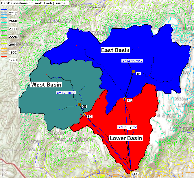
WMS 11.2 has improved the use of the TR-20 model by incorporating the WinTR-20 numeric model. WinTR-20 uses the same interface as TR-20. WinTR-20 contains upgrades to the source code with some changes to the input and output files. These changes have now been incorporated into WMS 11.2 to let you take full advantage of these features.

Export MP4 Files

MP4 files are now the default when exporting animations. You can export the MP4 files directly from the film loop wizard in WMS. MP4 files make sharing animations you’ve created in WMS easier.

The Toolbox in WMS 11.2
Toolbox

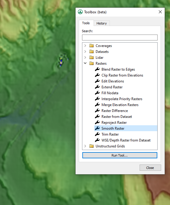
WMS 11.2 introduces the Toolbox which contains many tools for manipulating data and geometries. This is reached through the Toolbox macro. Of particular use for WMS projects are the tools related to working with rasters and lidar data allowing to trim, merge, and smooth this data along with many other options. The toolbox also contains many tools for working with coverages and datasets.

Color Ramp Options

The final new feature is the changes to the color ramp options. The color ramp now contains multiple preloaded color palettes. Options have been added to reverse pallets and to save your favorite palettes for easy access in the future. The preloaded palettes can also be duplicated and customized to meet your project's needs.

These are a few of the new features that come out with the release of WMS 11.2. Try out these features and more by downloading WMS 11.2 from the Aquaveo website today!

Blog tags: 

Exploring the Drawing Tools in WMS

When presenting a model in the Watershed Modeling System (WMS), you may need to clearly label locations or structures in your watershed model. For example, you may need a graphic with the names of your watershed branches clearly labeled. The Drawing Tools WMS provides a way to clearly annotate your watershed model. This blog post will cover some of the options and uses for these Drawing Tools.

Example of a drawing objects in WMS

The Drawing Tools contain options to draw objects including lines, rectangles, ovals, and text. When using the object creation tools, WMS provides attributes for changing the drawn object. Using the Select Drawing Object tool, you can double-click on a drawn object to pull-up the attribute options for the object. This includes options to change the line width, color, fill, arrows, and fonts.

It's important to note that drawing objects are layered. The first object you create will be below the next object you create. If you need to change how the objects are layered, the Drawing Tools contain tools for moving the objects forward or backward. To do this, select the object, then use the Move to Back, Move to Front, Shuffle Up, or Shuffle Down options to move the object.

You have the option to set a depth for the objects when creating new drawing objects. This depth is based on the project projection. Using the Drawing Depths command in the Drawing Objects menu, you can set a depth for the object you create. This can help make certain the drawing objects are above the grid, feature objects, or other items in the project.

It is important to note that the drawing objects are attached to the project projections. This means that drawing objects will stay fixed to the location of the model coordinates, not the Graphic Window position. This allows you to pan or zoom around your model and the drawing objects will stay fixed to the model location.

The drawing tools will be included when saving an image of the Main Graphics Window. This allows saving an image with annotations for use in presentation materials. To do this, use the Save As command and select the JPEG Image option for the file output.

The Drawing Tools are one of the options provided by WMS to let you make clear presentations for your watershed models. Try out the Drawing Tools in WMS today!

Blog tags: 

Switching Model Executables

The Groundwater Modeling System, Surface-water Modeling System, and Watershed Modeling System (collectively known as XMS) applications make use of multiple numerical models. XMS is packaged with the executables for each of these numerical models. At times, you may need to switch out which numerical model executable XMS uses.

In general, you will want to use the model executable that comes packaged with the XMS. XMS is coded to work with the specific model executables that are distributed with each version of the software.

There are some reasons you might want to change which model executable it used. It might fix a bug with the model executable. It might get you access to features in an older or newer version of the model executable. It might also help you test issues with the numerical model. Replacing the model executable isn't guaranteed to help with any of these, but it is one option for troubleshooting with all of them.

For all XMS applications, the numerical model executables to be used are selected in the Preferences dialog. If you already know where the model executable is, you can copy and paste the executable into the preferences dialog. To do so, use the following workflow:

  1. Copy the executable file path. If using Windows 11, right-click on the desired model executable and select "Copy as Path."
  2. If using Windows 10, open the Properties dialog from the right-click menu. Copy and paste the location path into a text document. Then, make sure to grab the file name ending in ".exe" as well. The executable path will be incomplete without that file name.
  3. In your XMS software, open the Preferences dialog from the Edit menu.
  4. Find the model executable that you want to change and click on the file path next to the name or the Browse button.
  5. In SMS or WMS, this will bring up an Open dialog. In the File name box, paste in the new executable path. If you are using Windows 11, make sure to delete the quotation marks at the beginning and end. Selecting Open saves the new model executable.
  6. In GMS, the model executable is editable without bringing up the Open dialog. Simply erase the former executable path and paste in the new one. As long as the path is a valid path and the path ends in ".exe", GMS will save it. Again, for Windows 11, delete the quotation marks.
  7. Finalize the model executable by clicking OK to exit the Preferences dialog. Otherwise, the executable will not save.
Example of model executables in the Preferences dialog

Now, there are some issues to keep in mind. As mentioned earlier, changing out a numerical model executable is not guaranteed to fix a particular issue or even improve the situation. Older or newer versions of the model executable may not always be compatible with your version of XMS. Sometimes the model executable is not compatible with a particular project. The new executable might even worsen the situation. If any of these things happen, you can reintroduce the original executable.

Check out the available model executables in XMS today!

Blog tags: 

Trimming DEMs in WMS

Have you imported a DEM into WMS but wanted to trim it down to use only a part of the original data? WMS has tools designed to help you trim DEMs that you have imported into WMS, so you can use only the part of the data that's relevant to your model. In this article, we explore the ways that this can be done in WMS.

Trimming a DEM can help eliminate extra data that is not necessary for your project. Having a DEM that is too large or contains data that is irrelevant to your project can cause your project to operate slower and in some cases can skew the results of your project.

One option for trimming a DEM is when it's part of the GIS Data Module as a raster. To do this, draw a feature object polygon in a map coverage then select it. With the polygon selected, you can right-click on the raster and select the Convert To | Trimmed Raster command. This trims the raster along the border of the polygon. The trimmed raster can be converted, if desired, to a DEM that will show up under the Terrain Data folder.

Of course, there are also tools for trimming files that are already in the Terrain Data Module as DEMs. These tools can be accessed either through the DEM menu when in the Terrain Data Module or through the right-click menu for a DEM item in the Project Explorer. In both places, the tools are found in the Trim submenu.

There are two ways to trim DEMs in the Terrain Data Module: by elevation and by polygon.

When trimming a DEM by elevation, WMS brings up a dialog that lets you specify the maximum elevation that you want the DEM trimmed to. The newly created DEM will have only elevations up to the maximum elevation set in this dialog. The contours will likely change to represent the new range of values in the trimmed DEM.

Example of trimming a DEM using a polygon in WMS

When trimming a DEM using a polygon, the program turns the mouse into a tool to click out the polygon in the Graphics Window. To finish the polygon, double-click where the last point is desired. Once the polygon is complete, the trimmed DEM is automatically created.

Note that a DEM created this way is still a rectangle. This is part of the definition of a DEM. However, only the points inside the drawn polygon will be active, so the displayed contours will end at the borders of the polygon you drew. The points that were outside the drawn polygon, which make up the rest of the bounding rectangle, are set to NODATA.

Take advantage of DEM trimming tools in WMS today!

Blog tags: 

Pages