Rebuilding an SRH-2D Restart File
By aquaveo on July 6, 2022Have you ever needed to rebuild an SRH-2D restart file for a project you were working on? Perhaps you lost the restart file or maybe you made modifications to your mesh, so the restart file is no longer valid for the model you have. Regardless of the cause, rebuilding a restart file can be a vital step in completing the model you're working on.
To start rebuilding your restart file, see if you can do a dry run of your simulation:
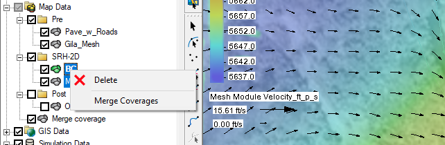
- Right-click on the simulation in the Project Explorer and select Duplicate. This ensures that the original simulation is preserved if needed.
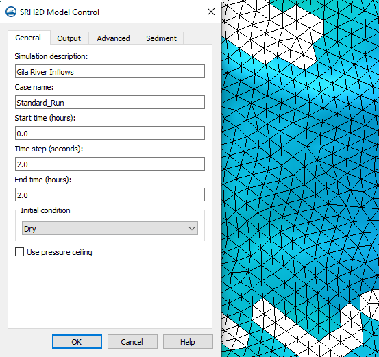
- In the newly-created simulation, right-click and select Model Control to open the Model Control dialog.
- In the dialog on the General tab, for the Initial Condition drop-down select "Dry".
Every run of SRH-2D creates restart files for the model. Initially, it creates a restart file for every time step as determined by the Output Frequency in the Model Control dialog. However, when the solution is loaded into SMS, the software only saves the restart file for the final time step. If a restart file for a different time step in the simulation is desired, then please complete the following before clicking Load Solution in the Simulation Run Queue dialog:
- Browse to where the project is saved.
- Double-click on the folder with the same name as the SMS project.
- Double-click on the SRH-2D folder.
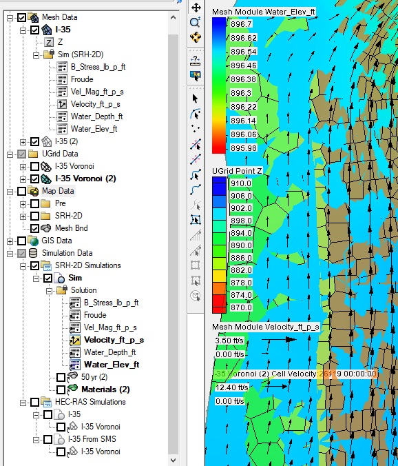
- Double-click on the folder with the same name as the simulation run. This is where restart files were written for every time step. The file that ends in "_TSO.dat" is a text file with information about which restart files correspond to each time step. Open it in a program that can read plain text files to make sure that you select the restart file with the desired time step. The restart files end in "_RST" followed by the time step number (e.g. "Standard_Run_RST12.dat").
- Once you have determined the restart file you want to save, copy and paste it in a different folder on your hard drive.
- Then click Load Solution in SMS.
SMS loads the results into SMS and keeps only the restart file for the final time step. It's important to remember that changing anything in the mesh necessitates the creation of a new restart file. Restart files should only be used with a model that uses the exact same mesh as the simulation that generated the restart file. Using the restart file with a slightly modified mesh might yield inaccurate results.
SRH-2 with SMS provides powerful tools for surface-water modeling. Use SMS today!