SMS

Registering an Image in XMS

Do you have an image that you would like to add to your project, but that image doesn’t have any coordinate information? Many projects require that you have an image or map that defines the proposed location for structures, wells, or other objects. In XMS (GMS, SMS, and WMS) the image needs to have coordinate information in order to correctly align with the project data. If your image does not have coordinate information, the Register Image dialog will appear.

Example of the Register Image dialog

To use the Register Image dialog, designate three points on the image and enter the coordinate information for those points. XMS will then use those coordinates to create the coordinate data for the entire image. It is possible to register an image using only two points, but three points is recommended.

If you do not know the coordinate information for any points on the image, here is a tip for getting coordinate information for the image.

  1. Click the Add Online Maps macro to open the Virtual Earth Map Locator dialog.
  2. Search for the area of your image by putting the name into the search bar and click Jump to Search Location.
  3. Be sure that the entire project bounds are within the window and match the area of your unregistered image.
  4. Download the new image and set the projection for this image.
  5. Note: you could just use this new image, but if the image you are trying to import shows the location of proposed structures, boreholes, etc., then you may need to still import the unregistered image.
  6. Outside of XMS, use a photo viewer to open the unregistered image.
  7. Compare both images and find three places where you can easily tell that the images match up.
  8. Now, in XMS, place your mouse over one of the three locations that you will need the geographical coordinates for.
  9. At the bottom of XMS you can view the coordinate information. Write down the coordinate information, then repeat in two other places.
  10. Now that you have all of the location coordinates you need to register the image, open the unregistered image file in XMS to bring up the Register Image dialog.
  11. Click the three points you have coordinate information for and enter in the coordinates that you wrote down earlier.
  12. After registering the image, check the alignment of the images if needed.
  13. Try registering an image for your project in SMS, GMS, or WMS today!

Blog tags: 

Reducing Scour in SRH-2D Sediment Transport

Do you have an SRH-2D sediment transport model that has an unreasonable amount of scouring? There could be several different issues in your model that are causing unreasonable scouring, however, SMS contains several different ways to fix this issue. This article will cover how to limit scouring so it is put to extremes in your model.

  1. Review the sediment loading on your boundary conditions for the sediment transport model. Double-click on one of your boundaries to check your sediment boundary conditions to review how the sediment loading has been defined. In the SRH-2D Assign BC dialog check and update the Sediment inflow section if needed.
  2. Example of scouring within an SRH-2D sediment transport model. The image on top shows the scour and the lower image it has been fixed.
  3. For your sediment transport SRH-2D simulation, go to SRH-2D Model Control and select the Sediment tab. Review the Particle diameter threshold section to make certain that the sizes are reasonable. Often having diameters that are too large causes scouring.

  4. Another place to review is the SRh-2D sediment material coverage. Right-click on the click Materials List and Properties. Under Gradation Curve, right-click on one of the materials and select click Edit Curve to bring up the Gradation Curve dialog. Review the gradation values and check for inconsistencies. Remember that the values need to be scaled from the smallest sand to the largest boulder. It is important to remember that the maximum number of functioning rows only goes up to nine. Any more than this will cause inconsistencies to appear.

    When the values that are entered in the Sediment Gradation Parameters are put to extreme values this is what will often cause the deep scour you may see in your model. A regular model will be smooth with very little deviation. A helpful resource to use if things are still not clear is the USBR website. They have example problems that you can follow.

These are just some of the tips for reducing scouring in your SRH-2D sediment transport models. For additional support for sediment transport with SRH-2D contact our technical support team. Try out SRH-2D with sediment transport in SMS 13.2 today!

Blog tags: 

Tips for Organizing the Project Explorer in SMS

SMS has many kinds of datasets, geometries, and simulations that could be added to your Project Explorer. These are useful features with essential roles in building a valuable project in SMS. But sometimes the Project Explorer gets very full and becomes difficult to navigate. This is when it can be useful to organize the Project Explorer to make things easier for you and those you work with. Today, we have some tips on how you might keep things organized so you can accomplish what you need to.

Example of Project Explorer Organization in SMS
  1. You might find it useful to name each new project element with a name that helps describe it. Descriptive names can help you find your project elements more quickly when you need to tweak something here or there. For example, you might have a materials coverage where the default Manning’s n is 0.015 and another one where you’ve changed it to 0.045. Labeling the materials coverage “n-0.015” and “n-0.045” could help you remember the difference between the coverages.
  2. You can add folders to organize items in the Project Explorer. For instance, you could group coverages according to which simulation you intend on using them for. Or maybe you have already imported a couple of rasters that you only need for one element of your project. You could put them together in a folder and collapse the folder in the Project Explorer. This will keep them out of sight while you don’t need them and could help you find them faster once you do need them. Note that solution data is automatically organized in folders in coordination with each simulation in the project.
  3. You can add notes to most elements of your project. To add a note, use the Properties… right-click command on an item in the Project Explorer and go to the Notes tab. There, you can leave notes for your colleagues (or yourself) about the item’s intended use or provide additional information that is not readily apparent. This is particularly helpful with simulations when you can add a note giving a summary of the key features of that simulation. Notes could also be used to indicate datasets you compared to get a new dataset. These can help everyone keep track of what function each thing serves in a given project.
  4. As you go through the project, it is recommended to delete what you’re not using. Not only does this organize the Project Explorer, it also frees up space in SMS. This can help you avoid slow processing time that can come from too many simulations. In general, we recommend you not have more than seven simulations in a project. It is also recommended to remove large rasters, shapefiles, or images after you are done using them. If you want to keep certain elements that you’re not using right now, you may want to minimize them or put them in a folder when not in use.

Using these tips, you will keep your projects organized and accessible. Make use of the organization tools for the Project Explorer in SMS today!.

Blog tags: 

Introducing the Toolbox in SMS 13.2

One of the new features added to SMS 13.2 is the Toolbox. The addition of the Toolbox allows multiple tools to be collected into one location. Many of these tools previously existed in other locations in SMS such as the Dataset Toolbox. In addition to these tools new tools have been developed for the Toolbox.

You can access the Toolbox using the Toolbox macro button located on the macro toolbar. Clicking the macro will open the Toolbox dialog containing a list of available tools.

The tools have been organized into folders in the Tools tab. Examples of folders include: Coverages, Datasets, Rasters, and Unstructured Grids.

  • Coverage tools are used to manipulate coverages and feature objects.
  • Datasets tools are many of the tools that have previously existed in the Dataset Toolbox and are used to manipulate datasets.
  • Rasters and Lidar tools are used to adjust and clean up raster and lidar data.
  • Unstructured Grid tools can manipulate and adjust unstructured grids (UGrids).
Example Compare Dataset Tool in the Toolbox for SMS 13.2

In addition, there will be folders for manipulating data related to specific numeric models. For example, there is a folder with tools that work with ADCIRC data.

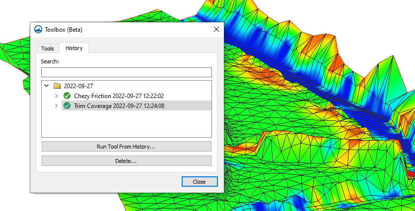
The Toolbox also contains a History tab. This tab keeps a record of all the tool runs used with your projects. As a result, it allows you to run the same tool again using the same settings. For example, you might use the Compare Dataset tool to compare the solution sets from two different simulations, then discover that there was an issue in one of the simulations. After you fixed the simulation and ran it again, you could use the history feature of the toolbox to run the Compare Dataset tool using the same settings as before.

The History tab also shows if a tool executed successfully or not. Furthermore, it lets you make notes on the different tool runs, allowing you to clarify why a tool run failed or what you were hoping to accomplish with a particular tool. This can facilitate collaborating with colleagues when working on the same project.

Additional tools will be added to the Toolbox in future versions of SMS. Try out the Toolbox in SMS 13.2 beta today!

Blog tags: 

Pages