GMS

Tips for Stochastic Modeling in GMS

Groundwater models often need to deal with a fair amount of uncertainty, especially when models have limited calibration data available to them. A stochastic modeling approach can be a useful option for dealing with this uncertainty by running a set of models to estimate the probability of certain outcomes, and GMS provides a few tools and methods to utilize this approach. This post will review some tips and tricks when it comes to stochastic modeling in GMS.

GMS provides three methods for stochastic modeling, using either MODFLOW 2000 or 2005. These are parameter zonation (which can be done either by a random sampling approach or a latin hypercube one), indicator simulations, and the Null Space Monte Carlo (NSMC) method.
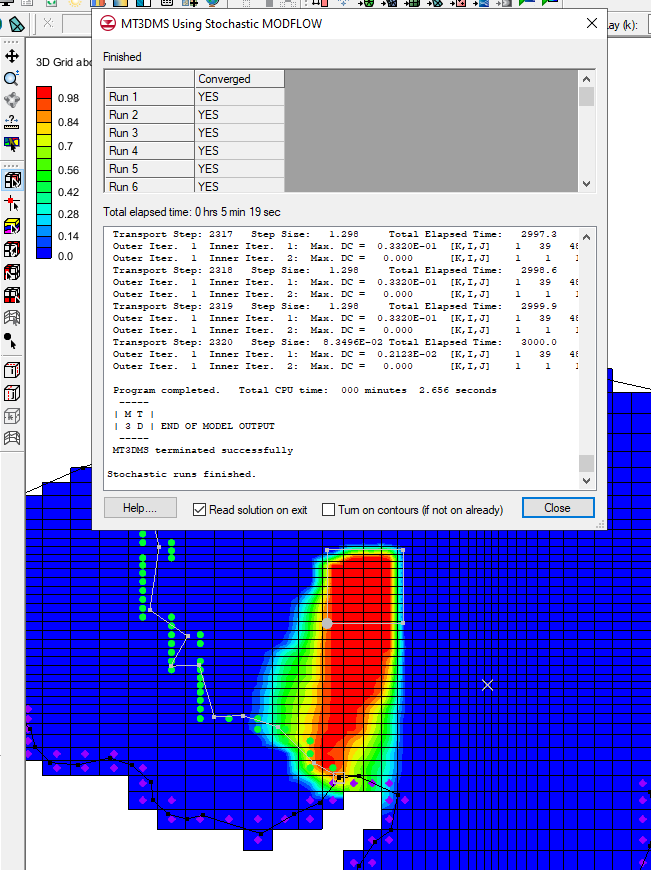
Running a stochastic model

When parameterizing a model and identifying which model inputs need to be randomized, aim for parameters with the highest uncertainty. But make sure to not select too many parameters, as having too many selected will require substantially large numbers of model runs to complete to be able to sufficiently explore parameter combinations, and this may become unreasonable. Also make sure that when defining key values to parameter zones, you don’t use values expected to normally occur in MODFLOW input. Negative values typically can accomplish this.

When it comes to indicator simulations, T-PROGS software is generally used to generate either multiple material sets or multiple MODFLOW HUF input sets to be used for stochastic simulation. Keep in mind that only a maximum of five materials can be used with the T-PROGS algorithm. This is an intentionally imposed limitation to keep data processing and user-interface from becoming too complex. While it is a hard limit, it is generally easy to condense borehole data down to five materials or less.

Once the stochastic modeling results have been generated, you can refine the results, either with the Risk Analysis Wizard or by using the Statistical Analysis command on a stochastic folder. The latter will create datasets for the mean, min, max, and standard deviation, which can be visualized by using 3D grid display options.

More information on stochastic modeling in GMS can be found at the Aquaveo XMS Wiki or reviewing the GMS tutorials for stochastic modeling.

Try out using stochastic modeling in GMS today!
Blog tags: 

Refining 3D Grids in GMS

It's common to need to refine part of a grid in your GMS project. For this reason, GMS provides a few tools and methods for refining parts of a grid. This post will review some of the options for refining 3D grids in GMS.

In general, when building a grid in GMS, you don’t want a grid that is too refined, as this will cause issues in the model run. You also do not want a grid that has cells that are too large to pick up vital information from key locations. To solve this, you can refine the grid in key locations.

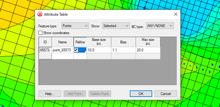
When generating a 3D grid or unstructured grid (UGrid) from a map coverage, you can use refinement points to refine specific locations. Refinement points require setting the map coverage up to have the Refinement option turned on. Then create points on the map coverage and define those points as refinement points. When converting the map coverage to a grid, the grid will be refined in the area of the points.

Defining a Refine Point in GMS

With an existing 3D grid, IJK boundaries can be added into the grid to refine an area. You can do this by using the Select i, Select j, or Select k tools to select a row, column, or layer, then right-click and select the Redistribute command. In addition, you can use the Grid | Redistribute layers command to redistribute layers.

If you have an existing UGrid, you can quickly refine the grid on a cell-by-cell basis. You do this by selecting a cell, then right-clicking and selecting the Refine cell command.

The above techniques work well for refining a small area of the grid or when refining grids that are not complex. Again, it is not recommended to overly refine a grid as this often causes issues to appear during the model run. If you do need to refine a large area of the grid, it is recommended to use a child grid.

Try out using the grid refinement tools in GMS today!

Blog tags: 

Importing Older Projects into GMS

Do you have an older GMS project that you need to open in the current version of GMS? Maybe you want to bring an older project into a newer version of GMS so you can make use of new features that have been added to GMS. Working with older projects can sometimes be tricky. Older versions of GMS are no longer supported and will break down over time. This article will explain more about why this happens and what can be done to get your older projects into a current version of GMS.

Generally speaking, GMS rarely has problems opening projects that are only a few years old. For example, the current version of GMS is version 10.5. Projects created in versions as far back as GMS 10.0 or 10.1 are likely to open without any issues For projects that are older, for example, projects that were created more than ten years ago, some issues may occur.

Over time, changes to the GMS interface, changes to the Windows operating system, and other factors may cause your project to not open in a current version of GMS. Also, how the data files were stored may cause the data to be unreadable.

When you have an older project that has failed to import into GMS, you can try a couple methods to get it into the current version of GMS.

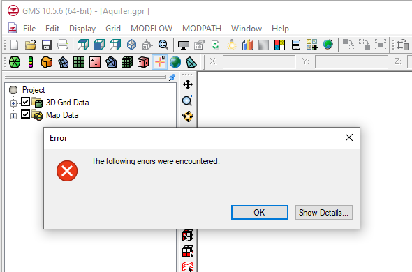
Error opening an older project in GMS 10.5

The first method is to migrate the project through different GMS versions. This is done by opening the project through consecutively more recent versions of GMS. For example, if your project was originally built in GMS 8.1 and does not open in GMS 10.5, you could start by opening the project in GMS 9.0, and then saving the project if it imports correctly. After this, try opening the project in GMS 10.0 and saving the project again. Finally, see if the project opens in GMS 10.5 and save it. While doing this stepping process, review the project to make certain it remained intact. Some corrections are likely needed because of how the migration process functions.

Aquaveo’s technical support team can help you obtain older versions of the software if you have a current license.

The second method is to rebuild the project in the current version of GMS using files from the original project. For MODFLOW projects, this is done by importing the native MODFLOW files. GMS can also read the MODFLOW files that are exported by GMS. You also may need to import individual files, such as the map files or grid files. Using this method you may not get everything out of the older project, but should be able to obtain enough to create a complete, working project.

If you need additional help with importing an older project into the current version of GMS or any of our software, contact our consulting team for assistance.

Blog tags: 

Importing a Shapefile to the DRN Package

Do you have drainage data in a shapefile that you would like to import into GMS to use for the drainage package in your MODFLOW project? Shapefiles are capable of holding a variety of information, including drainage data and other data used by MODFLOW. And a lot of software are capable of converting parts of a MODFLOW project into a shapefile.

If you have a shapefile with drainage data, it can be used for the DRN package in your MODFLOW simulation. This is done by using the following workflow:

  1. Use any of the methods to open a file to import your shapefile into your GMS project.
  2. One the shapefile has been imported into the GIS module, check to see if the conductivity values for the drains were imported with the shapefile. In most cases, this will happen automatically.
  3. In your MODFLOW conceptual model, create a map coverage with the drain option turned on in the coverage setup.
  4. Back in the GIS module, use the GIS | Shape > Feature Object command to open the GIS to Feature Objects wizard.
  5. In the first step of the wizard, make certain the drain coverage is selected and the correct shapefile is selected.
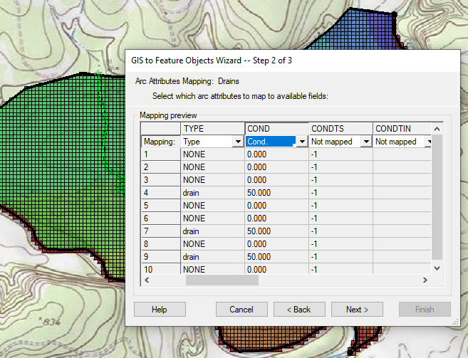
  6. In the second step of the wizard, make certain the Type and Conductivity columns are set correctly.
  7. Shapfile converstion to Drain feature objects
  8. After converting the shapefile to the map coverage, review the arcs and attributes. Clean up the coverage if needed.
  9. Finally, map the coverage to your MODFLOW model.

This workflow can be used for other MODFLOW attributes that are in shapefiles and need to be added to your MODFLOW project in GMS. For example, this workflow could be used to import a shapefile for wells, rivers, or other MODFLOW features. This workflow can also be used when importing MODFLOW projects into GMS where the MODFLOW project was created using other software.

Try out using shapefiles to import drain data into GMS today!

Blog tags: 

Pages