Understanding Software Graphics Mode
By aquaveo on September 5, 2023You may have noticed that GMS, SMS, and WMS software (collectively known as XMS) executables in your Start Menu offer a "Software Graphics Mode" option.The software graphics mode was created to help troubleshoot certain issues that might arise when using XMS. This blog post will explore the reasons for using software graphics mode.
The software graphics mode was specifically designed to address compatibility issues that may arise when there is a mismatch between the XMS software and the graphics card on your computer. While we aim to have XMS function smoothly on a variety of graphics cards, some cards may not be able to support the latest versions of XMS software.
When such a mismatch occurs, you may encounter difficulties while running the software. Some common issues that have been reported include:
- Objects disappearing from the Graphics Window when attempting to draw new objects.
- Complete disappearance of objects in the Graphics Window when changing views, even though they should remain visible.
- Appearance of objects in the Graphics Window that cannot be hidden or removed.
- Failure to successfully import specific graphics files.
- In certain cases, the XMS application fails to start.
- In other cases, the XMS application abruptly closes without warning.
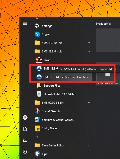
To overcome these challenges, utilizing the software graphics mode allows the XMS application to bypass the graphics card, effectively acting as a "safe mode" for XMS. It's important to note that this places a heavier burden on your machine's memory and processor. But this mode typically enables the XMS application to function without the issues caused by the graphics card. To access the software graphics mode, simply navigate to your Start Menu and select the desired XMS executable that has "Software Graphics Mode" in its title.
If utilizing the software graphics mode successfully resolves the issue you were experiencing, there is an additional step to consider: updating your graphics card drivers.
Updating your graphics card drivers often proves to be an effective solution for resolving compatibility issues between the XMS application and your graphics card. Follow the standard procedure for updating the graphics card drivers on your operating system. In some cases, you may need to visit the website of your graphics card manufacturer to obtain the latest drivers.
Once you have updated your graphics card drivers, you can typically continue using the XMS application without relying on the software graphics mode.
We hope this information proves valuable in understanding the purpose of software graphics mode and troubleshooting any related issues. Should you have any further questions or concerns, feel free to contact us.
This article is an update for a previous version found here.