Converting Elevations to Depths
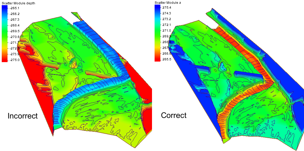
By aquaveo on March 13, 2019Have you ever found that the geometry data you’ve imported into your project is in elevation units, but the model you are using requires depth units? Using the the wrong topographic (elevation) or bathymetric (depth) data type can cause significant inaccuracies in your model results. It can also cause a lot of frustration. Therefore, it is always recommended to ensure you are using the correct data before running your model. SMS provides a way to change your data from elevation to depth (or vice versa) after it has been imported into your project.
Ideally, the correct bathymetry data will be used before assigning it to a geometry (2D Mesh, Cartesian Grid, etc.). When the original bathymetry dataset is incorrect, a new dataset should be created using the correct type (e.g., depth instead of elevation). The Data Calculator allows creating new datasets in SMS. This is done in the Scatter module by doing the following:
- Open the Dataset Toolbox
- Select the Data Calculator
- Select the scatter set
- Multiply the scatter set by -1
- Compute the new scatter set
- Use the new scatter set when generating the geometry
An elevation dataset can also be changed to a depth dataset with an existing geometry that has already been generated. This is done by doing the following:
- Open the Dataset Toolbox
- Select the Data Calculator
- Select the current elevation dataset and add it to the expression
- Multiply the dataset by -1
- Compute a new dataset
After creating the new elevation set, it needs to be designated as the elevation/depth for the geometry.
- Use the Data | Map Elevation command
- Select the new depth dataset
Now that you know how to change a dataset from elevation to depth, you can avoid the frustration of having the wrong data in your project. Try out the Data Calculator and other tools in SMS today!