We use cookies to make your experience better. To comply with the new e-Privacy directive, we need to ask for your consent to set the cookies. Learn more.


Best Practices for Working with MODFLOW Layers
Accurately defining aquifer layers is an essential step in building a reliable groundwater model. In the Groundwater Modeling System (GMS), layer elevations, thicknesses, and hydraulic properties help represent the subsurface geology and control how groundwater moves vertically and horizontally. Whether developing a new MODFLOW model or refining an existing simulation, understanding how model layers work can help prevent setup errors and improve results.
Understanding MODFLOW Layer Concepts
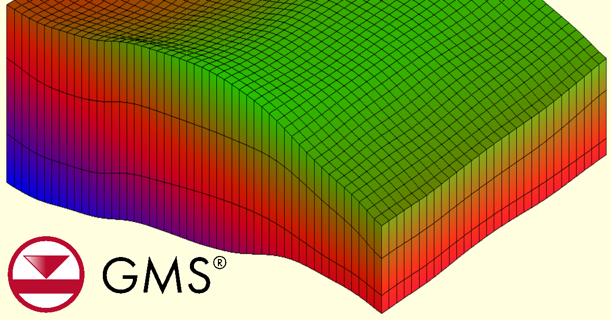
MODFLOW represents the subsurface as a three-dimensional numerical model divided into cells. In a traditional structured grid, cells are organized into layers, rows, and columns. Each layer represents a vertical interval of the modeled aquifer system, such as an unconfined aquifer, a confined aquifer, or a lower-permeability confining unit. Layer tops and bottoms define the model’s vertical geometry, while hydraulic conductivity and storage properties describe how groundwater moves and is stored.
A model layer does not always need to correspond to a separate geologic formation. A thick aquifer may require multiple numerical layers to represent vertical flow or contaminant transport, while some thin units may be combined when appropriate for the modeling objectives. The right level of detail depends on available geologic data, the processes being simulated, and the questions the model needs to answer.
Layer behavior also matters. In many traditional MODFLOW formulations, layers can be defined as confined or convertible, allowing saturated thickness and transmissivity to respond differently to changing groundwater levels. In MODFLOW 6, confined or convertible behavior is assigned at the cell level through the appropriate model data rather than simply applying one type to an entire layer.
Implementing Layers in GMS
GMS supports multiple approaches to building a MODFLOW model, including working directly with the numerical grid and using a conceptual model. The grid approach lets modelers assign properties to individual cells. The conceptual model approach allows features and parameters to be defined independently of grid resolution before they are mapped to the numerical model.
A practical workflow is to:
-
Define the stratigraphy. Gather borehole logs, geologic cross sections, elevation data, and other sources needed to estimate layer tops and bottoms.
-
Build the model layers. Create or configure the grid’s vertical discretization, ensuring layer elevations represent the intended aquifers and confining units.
-
Assign hydraulic properties. Specify values such as horizontal and vertical hydraulic conductivity and storage properties using appropriate data for each layer.
-
Map conceptual data when applicable. Use GMS tools to assign layer properties and boundary conditions from conceptual features to the numerical grid.
-
Review the 3D structure. Inspect cross sections and layer elevations before running the simulation to identify unexpected thicknesses, gaps, or overlaps.
GMS also provides tools for defining layer data from spatially varying stratigraphy, including workflows that use point data, interpolation, and geologic solids.
Tips and Common Pitfalls
Avoid assuming that every layer should have a uniform thickness. Real aquifers and confining units may change elevation across the model domain. Check that layer surfaces follow the available geologic evidence and that adjacent layers do not unintentionally overlap or leave gaps.
Be especially careful when assigning properties and boundary conditions to specific layers. A well screened across several units, for example, may require a different representation from a well completed in a single aquifer. Confirm that recharge, rivers, drains, and pumping stresses are assigned to the intended cells or layers.
Finally, inspect the model after mapping conceptual data and before running MODFLOW. Verify active and inactive cells, hydraulic properties, layer elevations, and boundary-condition placement. After the run, review heads and water budgets for unexpected behavior. A model that runs successfully is not necessarily a model with a geologically appropriate layer structure.
Thoughtful layer design in GMS provides a stronger foundation for groundwater flow simulations, calibration, and future transport modeling. Make use of GMS’s capacity to manage MODFLOW layers and download GMS from Aquaveo today!
November 17, 2026
|
View: 5
|
Categories: GMS
|
By: <a class="mp-info" href="https://aquaveo.com/blog/author/admin">Aquaveo Staff</a>
About the Author


Converting a NET File to an INP File
May 9, 2018
Performing a Silent Install of XMS (Passwords & Hardware Locks)
October 10, 2018
Computing Basin Curve Numbers in 9 Easy Steps
May 16, 2023
Performing a Silent Install for ALS
October 27, 2021
Tips for Finding Information on the XMS Wiki
September 25, 2019
Best Practices for Working with MODFLOW Layers
November 17, 2026
Mastering CMS Sediment Mapping
November 10, 2026
Save Time Selecting Polygon Arcs with SMS 14.0
November 3, 2026
Smart Guide to MT3D vs MODPATH
October 27, 2026
How to Calibrate a HEC-HMS Model for Peak Flow Accuracy
October 20, 2026