We use cookies to make your experience better. To comply with the new e-Privacy directive, we need to ask for your consent to set the cookies. Learn more.

Plotting Conductance for the DRN Package
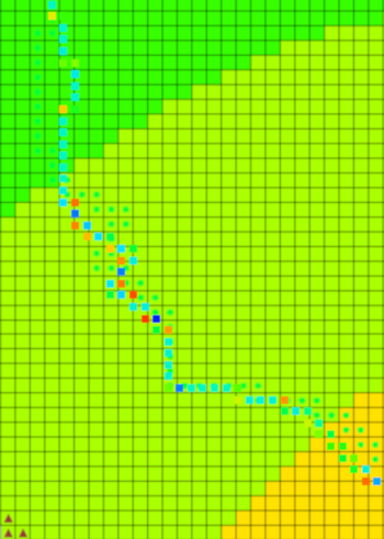
Are you looking for a way to contour the conductance of drainage areas in your groundwater model? If you have a large regional model containing areas with a dense drainage network (ditches, tile drainage, etc.), you can scale up this to represent a diffused drainage system. When doing this, there are not only single ditches simulated with the drain (DRN) package, but whole areas. Using GMS, you can create a contour of these drainage areas.
To create this contour, use the following workflow:
- Go to MODFLOW | Optional Packages | DRN to open the Drain (DRN) Package dialog.
- Make sure IJK is selected on the bottom in order to have the drains at their XYZ locations.
- Click the top left blank grey box to select all or select and drag to select all the data points.
- Copy the data and paste in a word processor such as Notepad++ and save the file.
- Back in GMS, select Open File and select the new text file. The text wizard should open up and already have delimited the file, but double check to make sure all the values are correct.
- Click Next then change the GMS data type to 3D Scatter points.
- If your file included elevations, you can make sure those are not mapped into your project by changing the dataset above to "Not Mapped".
- Otherwise, make sure your IJK cell values are matched up with their respective XYZ values and your conductance is set as the "Dataset".
- You may have to select the projection for this dataset in order for it to line up with your current project.
- You can then go to Display Options, select 3D scatter points on the left sidebar, and then turn on Contours if it has not already been turned on. You can check the contour options to see if the setup and coloring is to your liking.
Completing this workflow should cover all the drain points within the MODFLOW project. Try out contouring drainage areas in GMS today!
February 24, 2021
|
View: 354
|
Categories: GMS
|
By: <a class="mp-info" href="https://aquaveo.com/blog/author/admin">Aquaveo Staff</a>
About the Author

Performing a Silent Install of XMS (Passwords & Hardware Locks)
October 10, 2018
Tips for Finding Information on the XMS Wiki
September 25, 2019
Aquaveo 2024 in Review
December 30, 2024
How to Fix MODFLOW General Head Boundary Errors Using GMS
February 18, 2025
Help with Flow Direction and Accumulation
December 17, 2024
Connecting UGrid Points with Arcs
May 6, 2025
Simplifying Nested Grids with the Spectral Coverage
April 29, 2025
Converting Solids to Scatter Sets in GMS
April 22, 2025
Simplifying Watershed Modeling with Rho8 Tools
April 15, 2025
Enhanced Structure Options for CMS-Flow
April 8, 2025