We use cookies to make your experience better. To comply with the new e-Privacy directive, we need to ask for your consent to set the cookies. Learn more.
Problem Solving and the Fix Layer Errors Tool
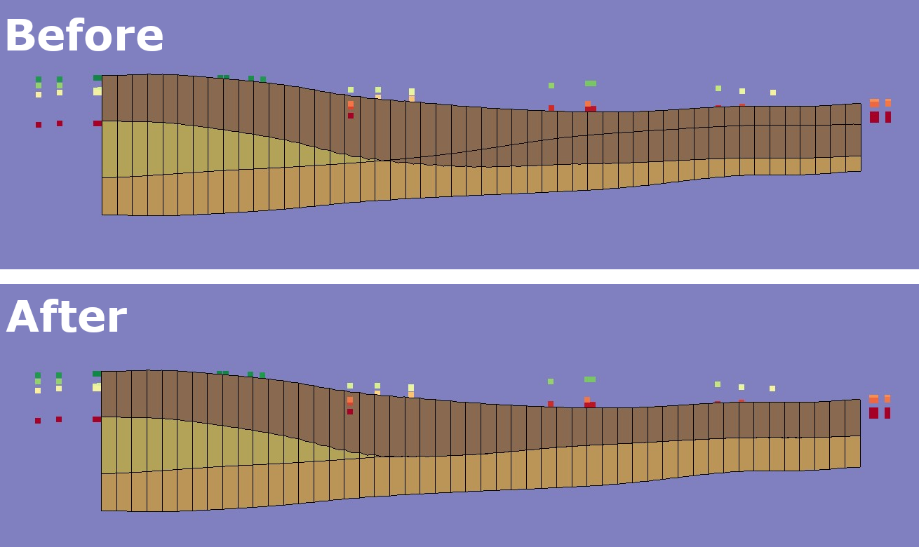
When creating multilayer models, defining layer data can be challenging. This is true for cases involving embedded seams, pinchouts, and truncations. Fortunately, Ground-water Modeling System (GMS) contains a suite of tools for interpolating and manipulating layer elevation data. With the tools in GMS), even complex geologic strata can be modeled quickly and easily. When interpolating layer data for the purpose of defining MODFLOW layer elevation arrays, there are often cases where the interpolated values overlap. In some cases, the best way to fix such a problem is to experiment with the interpolation options or to create some "pseudo-points" to fill in the gaps between sparse scatter points. In other cases, the overlap may correspond to a pinchout or truncation in the layer. In such cases, the elevations need to be adjusted so that there is a small but finite thickness for all cells in the overlapping region.
The first step in fixing layer errors is to use the Model Checker to determine if elevation overlaps occur. If they do occur, the Fix Layer Errors button at the top of the Model Checker dialog can be used to bring up the Fix Layer Errors dialog. Four options are available for fixing layer errors, including Average, Preserve Top, Preserve Bottom, and Truncate to Bedrock. The Average method is useful for modeling the transition zones adjacent to embedded seams. The Preserve Top method can be used to model truncated outcroppings. With the Preserve bottom method, at each cell where an overlap is found the bottom elevation is unchanged and the top elevation is adjusted to top = bot + min thickness. The Truncate to bedrock option differs from the other methods in that it can be used to alter several layers at once.
These are hypothetical scenarios that outline problems and solutions you may encounter when using the Fix Layer Errors Tool in GMS:

You are trying to construct a UGrid model that includes refinement around streams and pumping wells with refinement reserved for the top layers, and inactive cells with a thickness of less than 10 cm.
- You want a UGrid that includes refinement around streams and pumping wells, yet reserved for the top layers. You get the impression that reserved refinement is achievable only by using the preserve top method.
It is correct that the preserve top method is a way to apply refinement. The average method does not have any way to refine certain areas, unless the 2D geometry being used as the base already has that refinement. In that case, the refinement would be added to all layers. In other words, refine the 2D grid first, but use the TIN method to create the grid based on that refinement. Use your judgment on if method one works better for your elevation data. - You would like all cells with a thickness of less than 10 cm to be inactivated. Yet you find that the only way to inactivate cells less than 10 cm is by using the average method.
Using the average method and setting the minimum thickness to 0.1m ≠ inactive thin cells. It means cells less than the minimum thickness are not created. Cells are not inactivated until after a MODFLOW simulation has been added. As such, they cannot be inactivated during the creation process. If this is not the result, and there does appear to be thin cells for a TIN grid, further action would be required.
Access the latest version of GMS 10.8 to make use of the Fix Layer Errors tool today!


