We use cookies to make your experience better. To comply with the new e-Privacy directive, we need to ask for your consent to set the cookies. Learn more.

Generating a 3D Grid from Raster Data
Have you heard about the 3D UGrid from Rasters tool that’s new to the Groundwater Modeling System (GMS)? Previous versions of GMS required you to build a raster catalog and then use the “Horizons to Solids” command in order to generate a 3D unstructured grid (UGrid) when modeling stratigraphy. The 3D UGrid from Rasters tool, which is in GMS’s toolbox under the “Unstructured Grids” folder, streamlines this process by allowing the two previously separate processes to be set up in the same place and executed simultaneously.
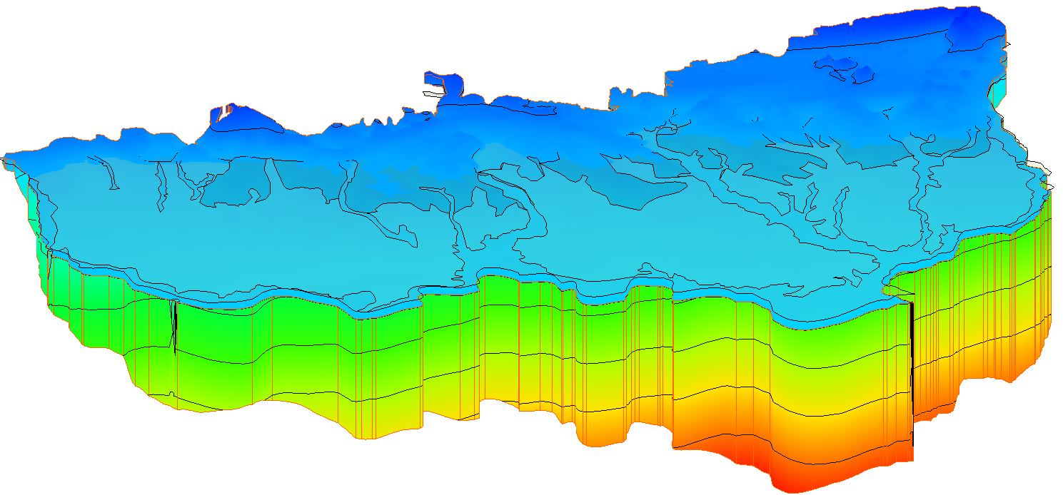
The base components for creating a UGrid with the 3D UGrid from Rasters tool are a 2D UGrid and multiple rasters. The rasters are then added to a table and assigned a horizon number. The term “horizon” refers to the top of each stratigraphic unit that will be represented in a corresponding solid, HUF unit, or 3D mesh layer. Horizons are ordered from the bottom up. For each raster you can choose to fill or clip the layer. Choosing “fill” tells GMS to use the raster to create a UGrid layer. Choosing “clip” tells GMS that any lower surfaces should truncate at that layer. You also have the option of creating sublayers between any rasters that have the “fill” option turned on. You can then set the relative size of each of the sublayers so that they are all proportional, or of differing sizes.
After setting all of the parameters for your UGrid in the rasters table, you then need to set a target location so that GMS knows to calculate elevations at the UGrid cell tops and bottoms or at the points. Lastly, you’ll need to define the minimum thickness that every layer must have, and choose a name for your new UGrid.
If you want more details about how the 3D UGrid from Rasters tool works, you can check out this page of our wiki. You can also look at the newest version of the Horizons with Rasters tutorial.
Head over to GMS, and use this new tool to simplify the stratigraphy modeling process.
February 13, 2024
|
View: 2873
|
Categories: GMS
|
By: <a class="mp-info" href="https://aquaveo.com/blog/author/admin">Aquaveo Staff</a>
About the Author

Performing a Silent Install of XMS (Passwords & Hardware Locks)
October 10, 2018
Computing Basin Curve Numbers in 9 Easy Steps
May 16, 2023
Converting a NET File to an INP File
May 9, 2018
Performing a Silent Install for ALS
October 27, 2021
Tips for Finding Information on the XMS Wiki
September 25, 2019
Comparing Multiple Design Alternatives in One Project
April 7, 2026
Incorporating MODFLOW 6 Groundwater Energy (GWE)
March 31, 2026
Essential DEM Clean-Up for Watershed Delineation
March 24, 2026
Essential Boundary Condition Guide
March 17, 2026
How to Delineate a Well Capture Zone Using MODPATH
March 10, 2026