We use cookies to make your experience better. To comply with the new e-Privacy directive, we need to ask for your consent to set the cookies. Learn more.

Creating UGrid Cross Sections in GMS
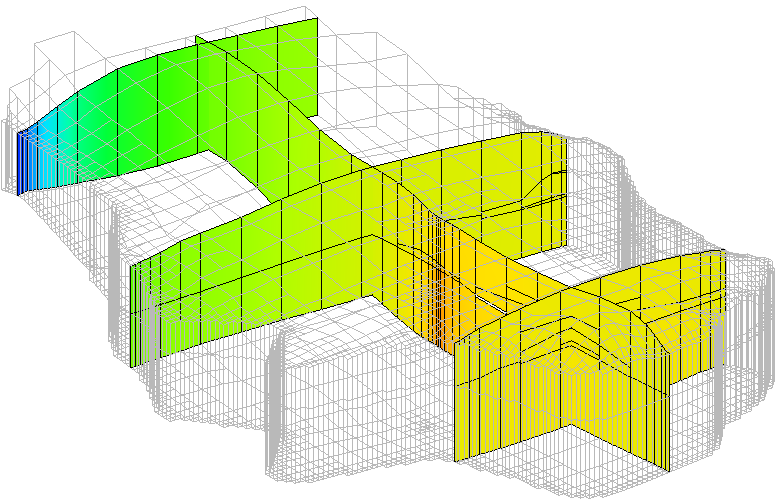
GMS 10.7 has added functionality for creating and viewing cross sections on unstructured grids (UGrids) in your GMS project. This article discusses this added functionality for creating UGrid cross sections and some things to keep in mind while using it.
You can use it anytime you want a quick view of the inside of a UGrid. Perhaps you want to review the contours of a MODFLOW 6 dataset or the materials in a specific section of a UGrid. With the Create Cross Section tool, you can quickly create a cross section that visualizes these values.
To use this tool, go to the UGrid Module in GMS and select the tool called Create Cross Section. Then, click out a line across your 3D UGrid in the GMS Graphics Window. This creates a new UGrid cross section, and a new cross section item appears in the Project Explorer under the active UGrid.
Depending on the display options you choose, it may be necessary to hide the UGrid to see the cross section you created. You can hide the UGrid by clicking the checkbox next to it in the Project Explorer. Even though the cross section is categorized under the UGrid in the Project Explorer, the cross section does not disappear when the UGrid is hidden. Another option for visualizing the cross section is to turn off face contours and cell faces in the display options for the active UGrid.
Regardless of the length of the line you click out, the Create Cross Section tool will create a cross section along your line from one end of the UGrid to the other. This tool does not create partial cross sections.
Moreover, this tool only creates cross sections on the active UGrid, even if other UGrids are visible and the active UGrid is not. Every UGrid cross section drawn is saved under the currently active UGrid in the Project Explorer.
If you accidentally create a cross section, it can be easily deleted by selecting it and using the delete command. This also allows you to create a UGrid cross section to quickly verify something, but then delete it just as quickly. It does not show up in your final model if you don't want it to.
These cross sections have a separate display options dialog that is accessed individually by right-clicking on the cross section in the Project Explorer. In the display options, the elevation offset for the UGrid cross section can be set. This allows for the cross section to appear above the UGrid for viewing. There are also options that allow you to decide which dataset the cross section contours represent. Many of the options relating to things like contours and cells are accessed by clicking the button labeled Other Display Options.
Creating UGrid cross sections makes visualizing 3D UGrid data more straightforward than before. Try the Create Cross Section tool in GMS 10.7 today!
November 16, 2022
|
View: 3321
|
Categories: GMS
|
By: <a class="mp-info" href="https://aquaveo.com/blog/author/admin">Aquaveo Staff</a>
About the Author

Performing a Silent Install of XMS (Passwords & Hardware Locks)
October 10, 2018
Computing Basin Curve Numbers in 9 Easy Steps
May 16, 2023
Converting a NET File to an INP File
May 9, 2018
Performing a Silent Install for ALS
October 27, 2021
Tips for Finding Information on the XMS Wiki
September 25, 2019
Comparing Multiple Design Alternatives in One Project
April 7, 2026
Incorporating MODFLOW 6 Groundwater Energy (GWE)
March 31, 2026
Essential DEM Clean-Up for Watershed Delineation
March 24, 2026
Essential Boundary Condition Guide
March 17, 2026
How to Delineate a Well Capture Zone Using MODPATH
March 10, 2026