We use cookies to make your experience better. To comply with the new e-Privacy directive, we need to ask for your consent to set the cookies. Learn more.
Velocity Vectors
Beginning with version 8.2, GMS can now generate velocity vectors using information from the MODFLOW cell-to-cell flow (ccf) file. Several pieces of information are required to compute groundwater flow velocity from a MODFLOW model. First, the amount of flow in the I, J, and K directions for a given cell is read from the CCF file. If a particular cell contains a boundary condition that is withdrawing water (such as a well) then the flow in the I, J, and K directions is decreased based on the amount of flow leaving the cell through the boundary condition. Next, the saturated area is calculated in the I, J, and K directions. For the I and J directions it is necessary to use the top and bottom elevations that are specified in MODFLOW's discretization package. If the particular cell is part of an unconfined aquifer then it is also necessary to get the computed head for the cell as the computed head is most likely below the top elevation of the cell. The final piece of information necessary for the calculation is porosity. Although porosity is not part of the MODFLOW inputs, using GMS you can specify porosity on a per cell basis. Once the flows, areas, and porosity are assembled the groundwater flow velocity is computed using the following equations:
Velocity.I = Flow.I / (SaturatedArea.I * porosity)
Velocity.J = Flow.J / (SaturatedArea.J * porosity)
Veloctiy.K = Flow.K / (Area.K * porosity)
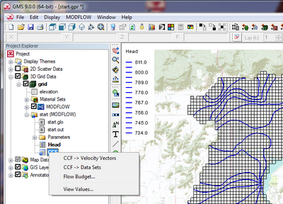
To create a velocity vector data set from a MODFLOW CCF file in GMS you simply right click on the CCF data in the GMS Project Explorer and select the CCF -> Velocity Vectors command.

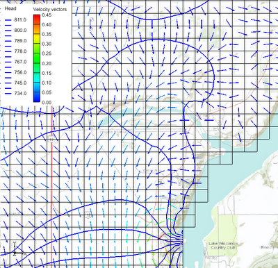
Once you have a vector data set you can adjust the display of the vectors by going to the Display Options dialog for the 3D grid and turning on the Vectors check box. If you select the Options button next to the Vectors check box you have further control over the display of the vectors.


