We use cookies to make your experience better. To comply with the new e-Privacy directive, we need to ask for your consent to set the cookies. Learn more.

Employing Hydraulic Conductivity in MODFLOW 6
For your Groundwater Modeling System (GMS) project, do you need a way to change hydraulic conductivity (K) values in MODFLOW 6? Although MODFLOW 6 doesn't currently assign conductivity through material properties like traditional MODFLOW does, there are a few alternative methods that you can use to easily modify K values.
Using a Map Coverage
One option is to use a map coverage through the conceptual model, which, in the latest version of the Groundwater Modeling System (GMS), supports Node Property Flow (NPF) values.
Set Up Your Materials
-
Click on the Materials macro to open the materials dialog.
-
Enter all desired material names and settings.
Set Up Your Coverage
-
Right-click anywhere in the Project Explorer and choose New | Conceptual Model….
-
From the Type drop-down, select MODFLOW.
-
Right-click on the new conceptual model and choose New Coverage….
-
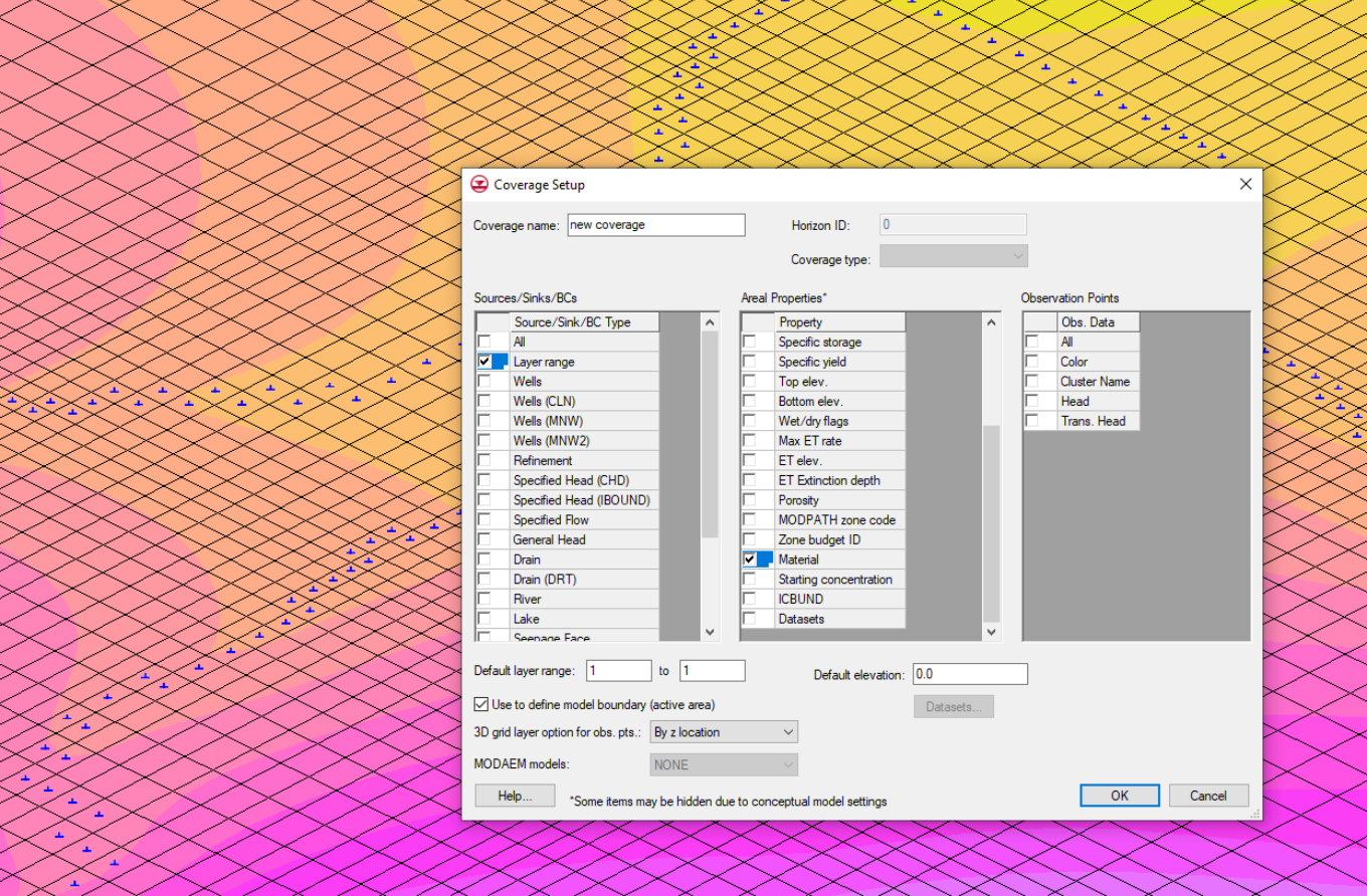
In the Coverage Setup dialog, select Layer range from the Sources/Sinks/BCs section and Material from the Areal Properties* section. Here, add any other attributes you might need.
-
In the Project Explorer, select the new coverage to make it active.
-
Use the Create Arc tool to draw out your desired material boundaries.
-
Click the Build Polygons macro to turn these boundaries into polygons.
-
Use the Select Polygons tool to choose one or more of the new polygons.
-
Double-click on the selected polygons to bring up the Attribute Table dialog and choose the desired material for each polygon, set the layer range, and fill in any additional attributes.
Map the Coverage to the Package
-
In the Project Explorer, right-click on the NPF package and choose Map from Coverage.
-
Select the new materials coverage.
Following these steps will fill the package arrays with data from the attribute table. Keep in mind that if the HK column was not enabled for the coverage, but HK was set in the materials dialog, HK will not be applied to the NPF package.
Using a Grid Dataset
If you are mapping a single attribute independently or no coverage option exists, you can create a dataset attached to the UGrid. First, create a coverage with the desired polygons as boundaries. Then, use the dataset to assign the attribute separately from the primary coverage.
Create a Dataset
-
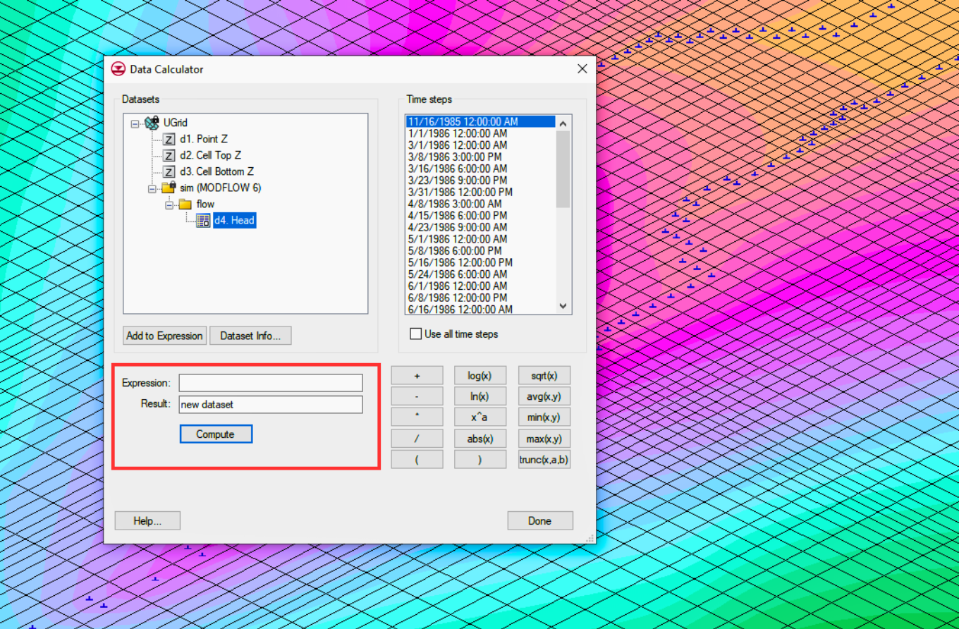
With the UGrid selected as active, go to Edit | Dataset Calculator….
-
In the dialog, name the dataset, select a default value, and click Compute.
-
In the following dialog, choose to map to cells. This creates a dataset where all cells have the default value.
-
In the Project Explorer, select one of your polygons in the coverage you made.
-
Right-click the selected polygon to choose Select Intersecting Objects….
-
Select your UGrid, which will select all the grid cells covered by the polygon.
-
Note that the Single layer option at the top of the screen must be deactivated if you wish to apply these choices to multiple layers.
-
With the cells selected, make the new dataset active.
-
At the top of the screen, you'll see an S field with the default value. Change this number to the desired value.
Apply the Dataset to the Array
-
Now that the dataset is built, double-click on the package you wish to update.
-
At the bottom of the GRIDDATA section, click Dataset to Array….
-
In the dialog that appears, select the newly created dataset. The array will be populated with the values entered in the dataset.
Mapping attributes to a package using a dataset attached to the UGrid is an effective method that allows flexibility in assigning values and ensures accurate data representation. This process can be replicated for all the tabs in the NPF package.
Download GMS and make use of hydraulic conductivity assignments in MODFLOW 6 today!
April 1, 2025
|
View: 5953
|
Categories: GMS
|
By: <a class="mp-info" href="https://aquaveo.com/blog/author/admin">Aquaveo Staff</a>
About the Author

Performing a Silent Install of XMS (Passwords & Hardware Locks)
October 10, 2018
Computing Basin Curve Numbers in 9 Easy Steps
May 16, 2023
Converting a NET File to an INP File
May 9, 2018
Performing a Silent Install for ALS
October 27, 2021
Tips for Finding Information on the XMS Wiki
September 25, 2019
Tips for Modeling Bridge Scour
May 19, 2026
Essential Guide to WMS Rain-on-Grid Modeling
May 5, 2026
Best Practices for Modeling Complex Geometries
April 28, 2026
Managing MODFLOW 6 Data: Lists, Copy Period & CSVs
April 21, 2026