We use cookies to make your experience better. To comply with the new e-Privacy directive, we need to ask for your consent to set the cookies. Learn more.
Understanding SRH-2D No Flow Boundaries
Do you want to understand more about how SRH-2D uses no flow boundaries? Occasionally, you can encounter various challenges regarding no flow boundaries. This post will review how no flow boundaries interact with SRH-2D in order to avoid potential issues with your SRH-2D model.

SRH-2D includes different types of no flow boundaries such as:
- Boundary condition arcs assigned to be a "wall".
- The elements touching a void in a mesh.
- The boundaries of a mesh that are not assigned to be inflow, outflow, etc.
Make certain to review all of your no flow boundaries. In particular, if you used a shapefile or another coverage to create your boundary condition coverage review all of the arcs on the coverage. In SMS, the default SRH-2D boundary condition is a "wall", so any arcs on the boundary condition coverage that are not meant to be no flow arcs should be changed or removed.
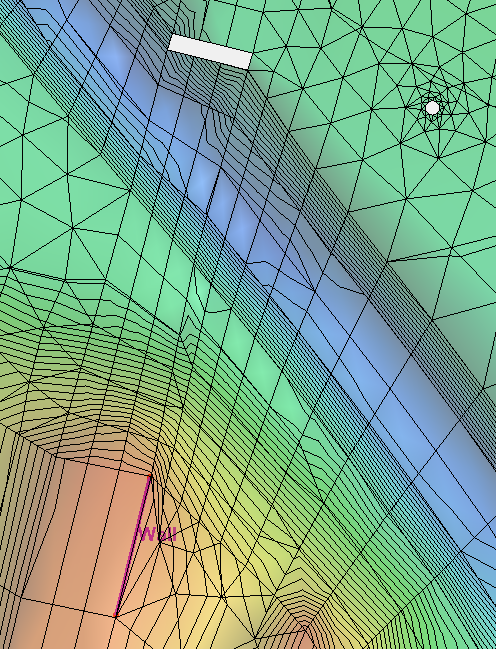
An important aspect to understand for no flow boundaries is that for every element they touch, SRH-2D is essentially being told that water can't flow past the boundary. This changes how SRH-2D computes the flow of water through the model. Large elements that are part of no flow boundaries can impact the model flow more than desired, because the smallest unit SRH-2D can process is a single element. SRH-2D is not designed to assign multiple flow values to a single element.
With this restriction on flow for single elements in mind, large elements can have a disproportionate effect on the model if left in key areas. Therefore, in most cases it is important to make sure that elements around key areas of the model should be more refined. Larger elements should be left in less important areas where they will have less impact.
Now that you understand a little more about no flow boundaries, try out SRH-2D in SMS 13.1 today!


