We use cookies to make your experience better. To comply with the new e-Privacy directive, we need to ask for your consent to set the cookies. Learn more.

Tips for Pressure Zones with Overtopping in SRH-2D Models
Does your SRH-2D project have a box culvert or pressure zone with overtopping that is proving to be a bit difficult to get correct?
Box culverts or pressure zones with overtopping are common features added to many SRH-2D models. Depending on how the pressure zone is created in your Surface-water Modeling System (SMS) project, this can be a tricky process for SRH-2D to handle. Here are some steps and tips for creating this feature successfully in SMS.
1 Use Quadrilateral Elements
Create quadrilateral elements between the boundaries of the pressure zone. Using quadrilateral elements tends to increase the stability and reliability of the SRH-2D model run. Quadrilateral elements can be created in one of two ways.
The first is to create the quadrilateral elements when creating the 2D mesh. Create a polygon for the area between and around the pressure zone. Assign this polygon with the Patch mesh type in the 2D Mesh Polygon Properties dialog.
The second method is to create the quadrilateral elements directly in the mesh using the Split/Merge tool and the Switch Element tool. This can be time-consuming, so it is only recommended for small adjustments.
2 Create Voids
Create voids in the mesh on either side of the pressure zone. There are two options for creating these voids, but one option seems to work better.
The first option, and the more stable one, is to create the voids on either side of the pressure zone when generating the mesh. Create the voids as polygons and assign them the None mesh type. It is generally best to make each void a quadrilateral polygon to imitate the thickness of a concrete wall or barrier.
The second option is to generate the mesh then use the Select Elements tool to select and delete the elements where the voids should be. Using this method requires renumbering the mesh nodes. There is a risk that you will not be able to delete all of the nodes related to the elements which can make your mesh unusable to SRH-2D.
3 Assign Boundary Conditions
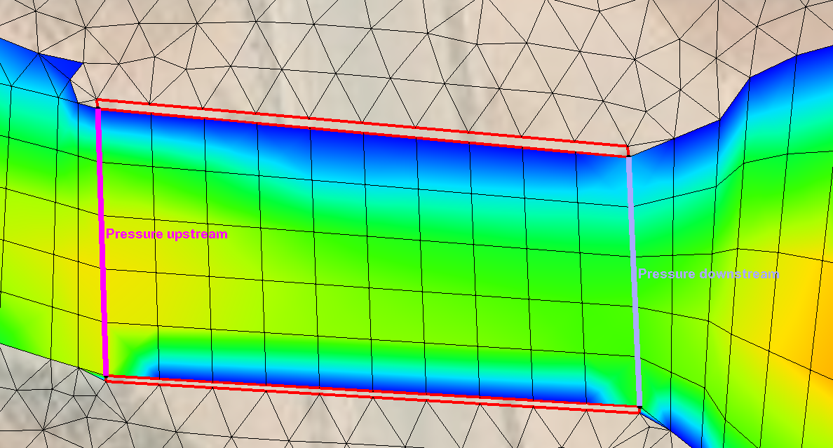
Two arcs are needed to define the pressure zone. Each arc should be created on an SRH-2D boundary condition coverage. When creating the arcs, make certain all 2D mesh elements between the arcs are quadrilateral elements. Also, it is advisable to have at least one row of quadrilateral elements just past the downstream arc.
Once the arcs have been drawn, select both arcs and open the SRH-2D Linear BC dialog. Set both arcs to the Pressure type, making sure the correct arc ID is assigned to upstream versus downstream, and turn on the Overtopping option.
Both the boundary condition coverage and the 2D mesh can be added to your SRH-2D simulation to have a pressure zone with overtopping included in the results.
Try out adding a pressure zone in SMS today!
September 3, 2024
|
View: 3037
|
Categories: SMS
|
By: <a class="mp-info" href="https://aquaveo.com/blog/author/admin">Aquaveo Staff</a>
About the Author

Performing a Silent Install of XMS (Passwords & Hardware Locks)
October 10, 2018
Converting a NET File to an INP File
May 9, 2018
Computing Basin Curve Numbers in 9 Easy Steps
May 16, 2023
Performing a Silent Install for ALS
October 27, 2021
Tips for Finding Information on the XMS Wiki
September 25, 2019
SRH-2D Inflow & Outflow Best Practices
June 30, 2026
Troubleshooting Projection and Coordinate System Issues
June 23, 2026
How to Determine Soil Texture Using NRCS Soil Data
June 16, 2026
Diagnosing Costly Model Stability Issues
June 9, 2026
New Display Enhancements in GMS 10.9
June 2, 2026