SMS

Two Tools for Creating a Raster from a Dataset

Do you have solution data that you want to export as raster data? The Surface-water Modeling System (SMS) provides two tools to help you create rasters from datasets. In this blogpost we will discuss the WSE/Depth Raster from Dataset tool and Raster from Dataset tool as well as the uses for both these tools and the differences between them.

Example of the WSE/Depth Raster from Dataset tool

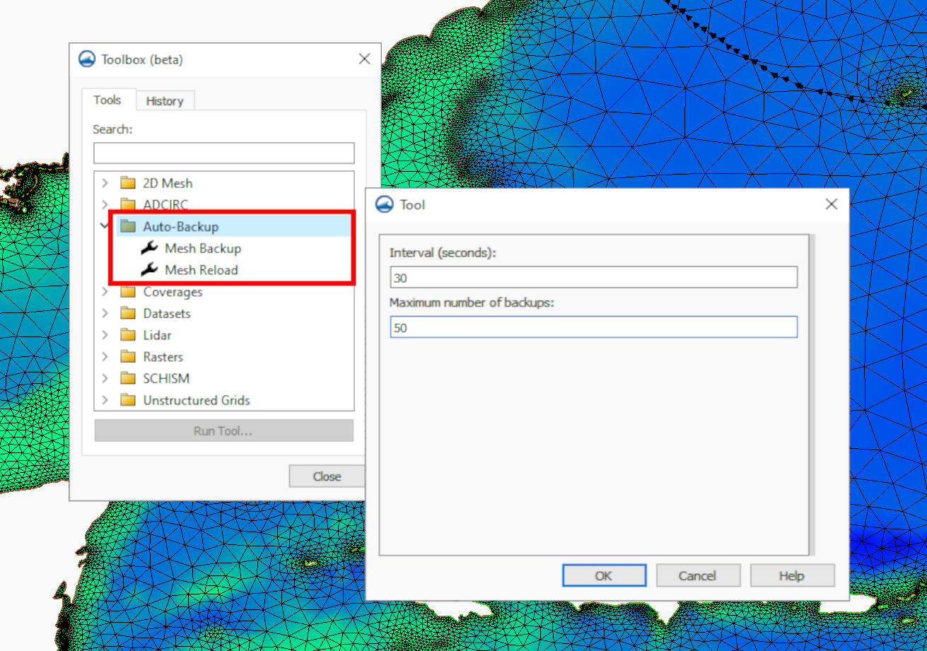
WSE/Depth Raster from Dataset tool and Raster from Dataset tool are two separate tools in the SMS Toolbox. Each addresses the process of converting datasets to rasters, but with some differences.

To start, it should be noted that both tools are designed for creating raster data from solution datasets. This means that your project should contain solution data from a successful model run. Also, both tools allow you to define the pixel size of the resulting raster.

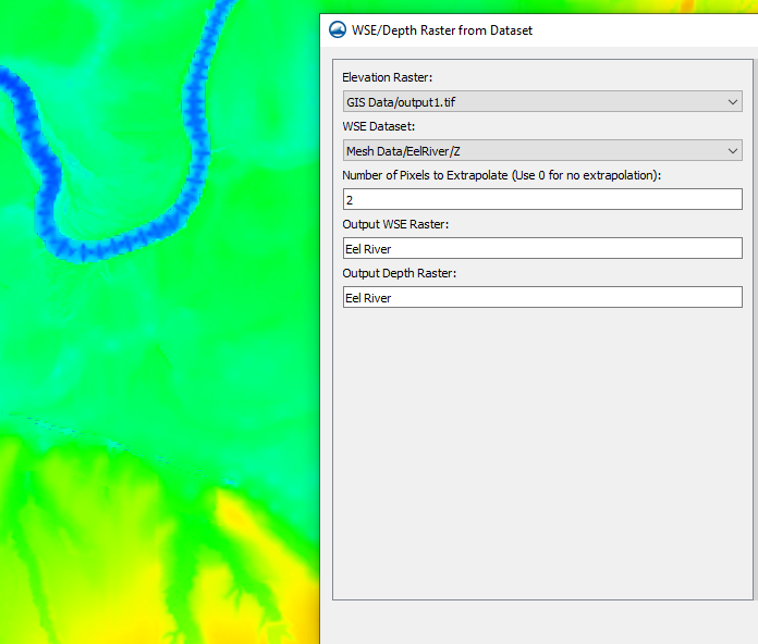
The WSE/Depth Raster from Dataset tool creates a raster based on water-surface elevation (WSE) or depth data. The tool requires that you have a geometry containing a WSE or elevation solution dataset in your project and that you have a raster containing the project elevation. It can extract both a WSE raster and a depth raster from a single tool execution. The tool is designed specifically to work with the bathymetry data. Other datasets may be converted incorrectly when using the WSE/Depth Raster from Dataset tool.

For other solution dataset on a geometry, the Raster from Dataset tool can create a raster from those datasets. This tool will work with datasets on various geometries including meshes, scatter sets, and unstructured grids (UGrids). The tool also allows you to use a raster template to define the output origin, activity, and possible resolution.

Now that you know some of the similarities and differences between the WSE/Depths Raster from Dataset tool and the Raster from Datasets tool, try out both of these tools and other features in the SMS Toolbox today!

Blog tags: 

Speed Up Edits Using Mesh Subsets

While working with meshes in the Surface-water Modeling System (SMS), you may have noticed that the more elements there are in the mesh, the slower the processing speed gets when making edits. Subset edit mode allows you to edit just one portion of the mesh at a time, which can increase the processing speed considerably. You can access the “Edit Subset” option by selecting the elements on the mesh you want to work with and right-clicking in the Graphics Window.

Using the Edit Subsit mode

Working within the edit subset mode was designed to let you work on a large mesh without overtaxing your machine’s memory and processing power. When you select a section of the mesh and enter subset mode, SMS will stop displaying the parts of the mesh that were not selected. This allows SMS to ignore the elements and data on the parts of the mesh outside of the subset. This can help free up computing power while making changes to the subset mesh. When you are done making your changes, you can exit the subset mode to have SMS include your changes in the full-sized mesh.

While in subset mode, the mesh in the Project Explorer will be tagged with the (subset) suffix. Some of the specific commands that you can use in subset edit mode are:

  • Commit Subset: this command takes you out of subset edit mode, and merges the changes made to the mesh subset with the rest of the mesh.
  • Revert Subset: this command takes you out of subset edit mode, but does not retain any of the changes made to the mesh subset.

You may notice that "Refine" is listed as an option in the right-click menu while subset edit mode is active, however you are not able to refine elements in a subset. If you select "Refine" an error will appear stating "Command not available in subset edit mode."

Some actions that you are not able to perform while in subset edit mode are:

  • Making changes on the border of the mesh subset.
  • Creating a new mesh.
  • Running a numerical model.
  • Changing attributes such as boundary conditions on nodes, nodestrings, and elements.
  • Renumbering node/nodestring/element IDs.

Head over to SMS and see how subset edit mode speeds up the processing time when editing large meshes today!

Blog tags: 

Creating Reliable Arc Pairs for SRH-2D

SRH-2D models in the Surface-water Modeling System (SMS) often use pairs of arcs to represent structures like culverts, weirs, bridges, and gates. For some projects, it matters for SRH-2D about how these arc pairs are drawn, and improperly drawn arcs can stand in the way between you and a successfully run model.

Arc pairs in SRH-2D models need to be drawn from left to right as if you are looking from upstream to downstream. This can get quite confusing, so here are a few tips for how to be able to tell which direction your arcs need to go by making use of display settings in the Display Options dialog.

Using vectors to find stream direction

If you’re not sure which direction is upstream and which is downstream, select 2D Mesh from the list on the left of the Display Options dialog and turn on Vectors. This requires having a dataset associated with the mesh that contains vector values. The vectors will display the direction the water is flowing, which makes it easy to be able to tell where upstream is. Now, to draw the arcs in the correct direction, imagine you are standing upstream and looking downstream. Then start the arc on your left and end it on your right. Both arcs need to be drawn in the same direction.

What do you do if you’ve already drawn the arcs and then you try to run your simulation and it fails? If the failure is caused by misdrawn arcs, the error will read "Program stopped due to the following: Linked Pair nodestring direction is wrong; please reverse them". The fix is simple if you have only one pair of arcs on your mesh: select both arcs in the Graphics Window, right-click, and select Reverse Arc Direction.

The Reverse Arc Direction command

However, the existence of more than one arc pair can make solving this error a little more complicated. Rather than going around and either redrawing or reversing all the arcs, here's what you can do to pinpoint the problematic pair. First, open the Display Options dialog. On the Map tab check the box next to Annotations and click the Options button. In the Arc Annotation Options dialog, turn on Show arc direction arrow. Doing this will add arrows to the arc, pointing toward the end. This makes it easy to look at the arcs and see which ones are facing the wrong direction, at which point you can use the same steps as above to reverse the arc direction.

Head over to SMS and use this guide to help your SRH-2D model run more smoothly today!

Blog tags: 

Using Mesh Auto-Backup

Needing to save and reload older versions of your 2D mesh in the Surface-water Modeling System (SMS)? SMS 13.3 has a new set of tools that let you do just that. The Auto-Backup folder included in the Toolbox contains the Mesh Backup and the Mesh Reload tools. These tools let you save past versions of a 2D mesh while you are editing the mesh. If you discover a change to the mesh was undesirable, you can load a version of the mesh before the change was made.

SMS uses 2D meshes for a wide variety of models including, but not limited to, ADCIRC and SRH-2D, as well as generic models. Using the new Auto-Backup tools, you are free to make as many edits to the mesh as you need knowing you can recover the previous versions. This blog post reviews how the Auto-Backup tools work.

Mesh Backup Tool
The auto-backup tools

The Mesh Backup tool creates a series of backups at specified intervals for a specified number of iterations. Both the interval and the number of backups are determined by the user in the tool’s dialog. The default values are a mesh backup every 20 seconds, 10 times. These values can be changed to whatever works best for your project, however, it is recommended that you limit the amount of backups to roughly 200 or less.

When you run the tool, a dialog labeled Turn on/off auto mesh backup will appear. This dialog means that the tool is on, and will run in the background while you work on your mesh. This dialog is intended to stay open while you work on your mesh. Clicking Cancel will turn off the tool. While the tool is running, SMS checks to see whether or not a change has been made to the mesh every time the specified time interval has elapsed, and then creates a backup copy.

Running the mesh backup

The log portion of the Turn on/off auto mesh backup dialog keeps track of how many backups have been made for the mesh. It will also tell you if there was an interval where no changes were made to the mesh. In cases where no changes were detected, a backup copy of the mesh during that period will not be stored.

Mesh Reload Tool

The Mesh Reload tool is where you can access the mesh backups. Naturally, this means that you have to run the Mesh Backup tool before anything will be available to reload. The Mesh Reload tool dialog contains a dropdown menu with all the backup meshes labeled by timestamp. The dropdown menu will often not contain every single time stamp, because there will likely be some time stamps where no changes to the mesh have been made.

Using the Mesh Reload tool does not erase the current mesh, or backtrack any changes that you’ve made. It will simply add a copy of what the mesh looked like at that time stamp under the "Mesh Data" folder in the Project Explorer. Try out the new Auto-Backup tools in SMS 13.3 today!

Blog tags: 

Pages